Energy storage system

a technology of energy storage and energy storage, applied in steam engine plants, mechanical equipment, machines/engines, etc., can solve the problems of inability to achieve adiabatic or no-co2 operation, low coefficient of performance of heat pumps, and low cost effectiveness of various heat sources, so as to increase the work production of compressed air

Inactive Publication Date: 2011-01-27
ELECTRIC POWER RES INST INC
View PDF28 Cites 27 Cited by
  • Summary
  • Abstract
  • Description
  • Claims
  • Application Information

AI Technical Summary

Benefits of technology

[0008]According to one aspect of the present invention, an energy storage system includes a compressor for compressing ambient air; an air storage reservoir adapted to store compressed air from

Problems solved by technology

Advanced diabatic CAES cycles generally include a combustion turbine and, as a result, cannot obtain or approach adiabatic or no-CO2 operation.
The problems and disadvantages with various adiabatic approaches centers on the suitability and cost effectiveness of the various heat sources.
For example, geothermal sources are in the 200 to 400° F. range, with some geographical exceptions, compression heat from standard industrial compressor trains is in the range of 200 to 500° F., and high temperature industrial heat pumps are limited to temperatures of about 400° F. with a low temperature shift at this output temperature—meaning they cannot pump heat all the w

Method used


Image

  • Energy storage system
  • Energy storage system
  • Energy storage system

Examples


Embodiment Construction

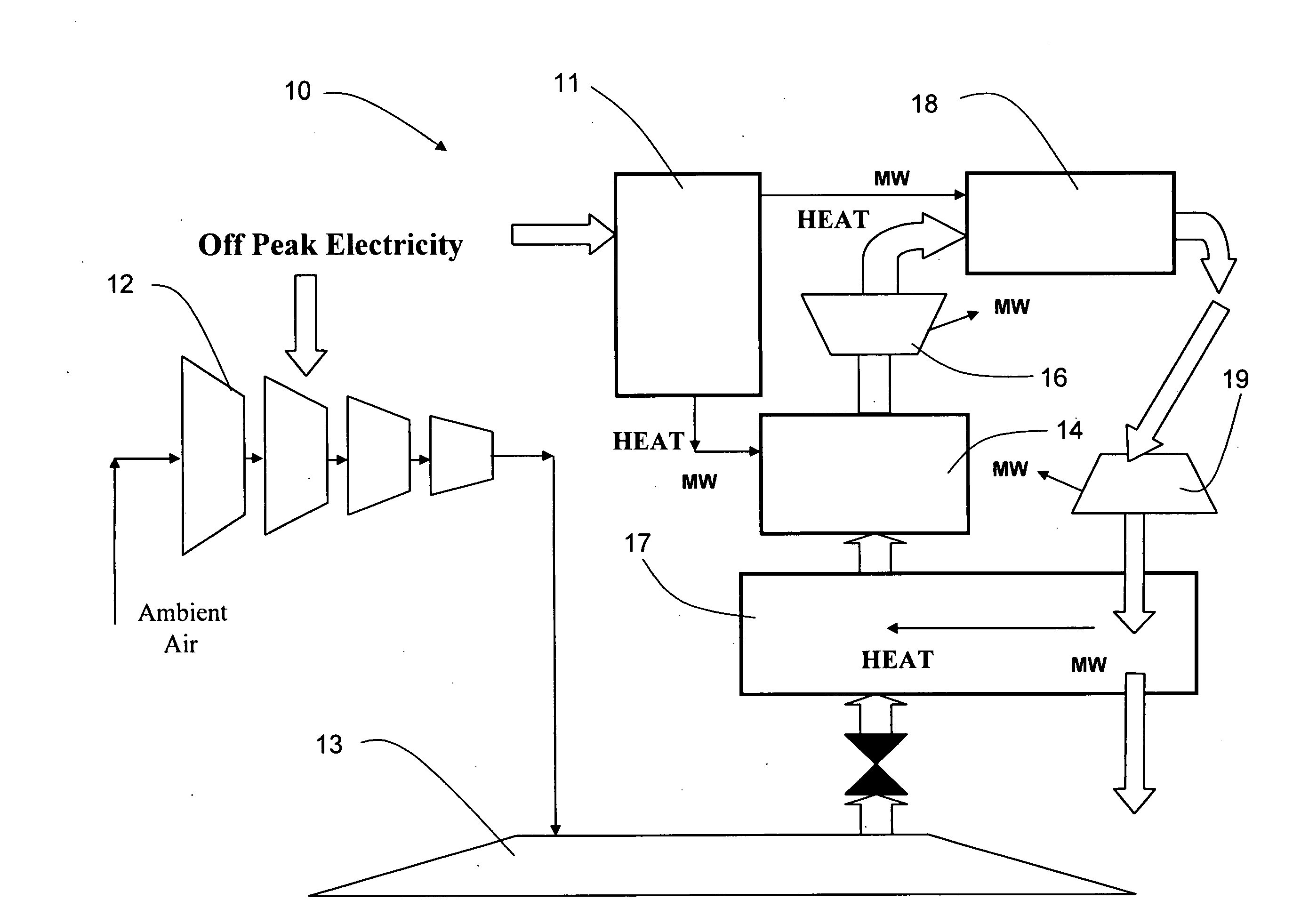
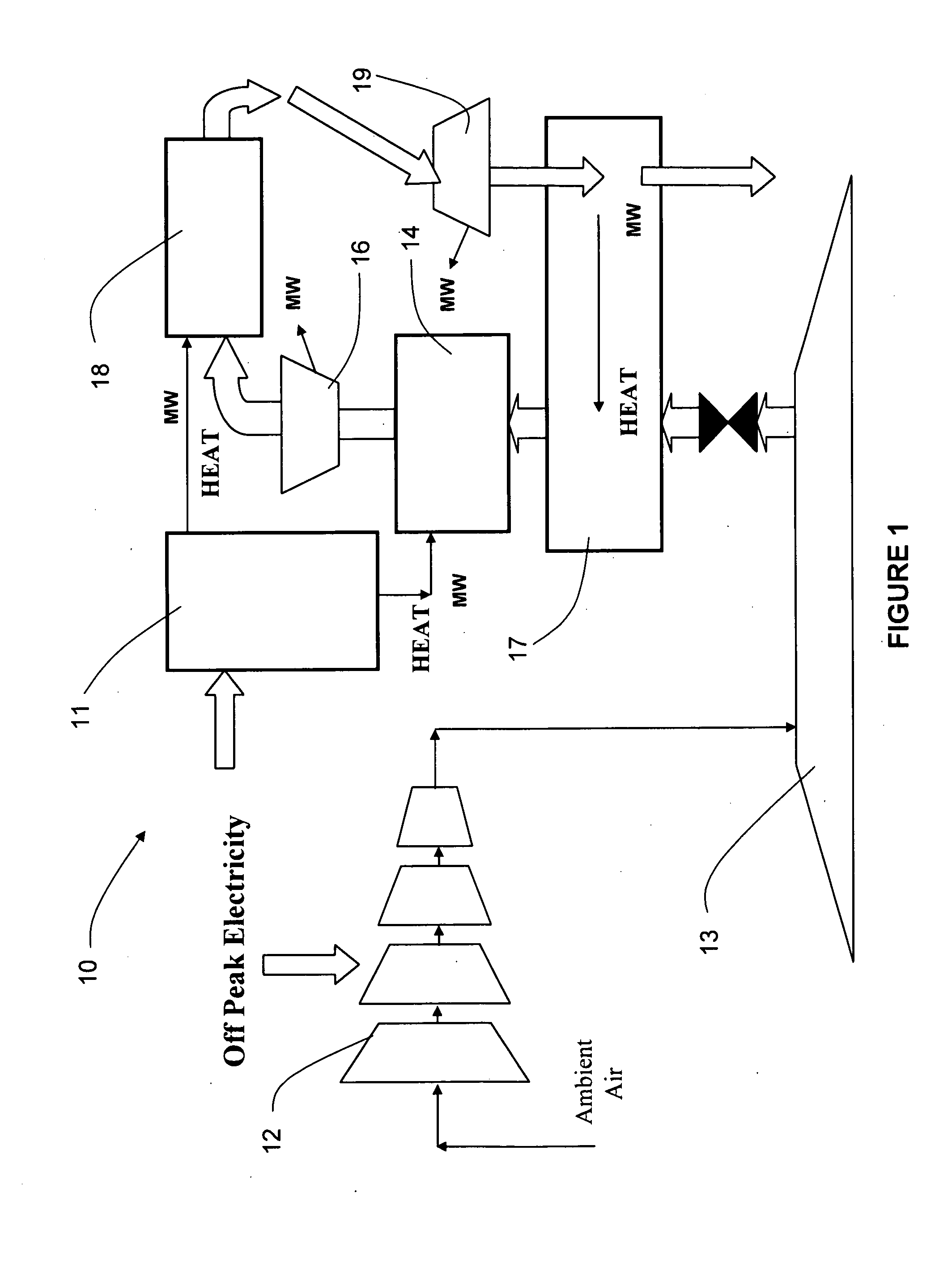
[0014]Referring to the drawings, an exemplary bulk energy storage system according to the present invention is illustrated in FIG. 1 and shown generally at reference numeral 10. The bulk energy storage system 10 is a compressed air energy storage (CAES) system that may be used in applications such as wind integration, arbitrage, load leveling, spinning reserve and ramping duty. The CAES system 10 attains a zero heat rate with direct heating of a thermal energy storage (TES) system 11 using off-peak, or any relatively low cost, electric power. Direct heating provides for high energy retention and efficiency compared to other heating options. Electric power is used for both air compression and heating of a TES material, such as molten salt, contained in the TES system 11. Supplemental heating of the TES material may also be obtained from other sources such as geothermal, solar thermal, and biomass sources with low or no net carbon dioxide emissions.

[0015]As shown, the CAES system 10 i...


PUM


Abstract

A compressed air energy storage (CAES) system encompassing direct heating. The compressed air energy storage system includes a compressor for compressing ambient air, an air storage reservoir, and a thermal energy storage system. The air storage reservoir is adapted to store compressed air from the compressor. The thermal energy storage system is adapted to supply heat to the compressed air energy storage system such that the compressed air is heated to increase work production of the compressed air. The thermal energy storage system is heated using off-peak electricity.

Description

BACKGROUND OF THE INVENTION[0001]The present invention relates generally to an energy storage system, and more particularly to a compressed air energy storage (CAES) system encompassing direct heating. Electrical and / or mechanical power is used for both air compression, as well as heating of the expansion airflow through the use of a thermal energy storage (TES) system.[0002]CAES systems dampen imbalances between power generation and power usage (act as generator or a load), as well as providing the capability of storing inexpensive or unwanted electrical power. CAES systems store this power through air compression. During power production the expanding air is heated to increase power production, to more efficiently use the stored air, and to avoid cryogenic expander requirements. Diabatic CAES systems rely on premium fuel combustion to achieve the required heating, either through individual combustors or combustion turbines.[0003]Adiabatic or no-fuel CAES systems are becoming more ...

Claims


Application Information

Patent Timeline
IPC IPC(8): F02C1/05F02C6/16
CPCY02E60/15F02C6/16Y02E60/16F02C7/08F15B21/14
Inventor WRIGHT, SEAN EDWARDLORDAN, RICHARD JOSEPHSCHAINKER, ROBERT B.
Owner ELECTRIC POWER RES INST INC
Why Eureka
Try Eureka