Method and device for controlling a fuel metering system

a fuel metering system and fuel metering technology, applied in the direction of electric control, machines/engines, instruments, etc., can solve the problems of increasing rail pressure and in particular damage to the injector

Inactive Publication Date: 2011-01-27
ROBERT BOSCH GMBH
View PDF6 Cites 14 Cited by
  • Summary
  • Abstract
  • Description
  • Claims
  • Application Information

AI Technical Summary

Benefits of technology

[0005]The rail pressure is an important variable required for controlling the internal combustion engine. It is therefore advantageous if another rail pressure signal is available in addition to the output signal of the rail pressure sensor.

Problems solved by technology

This results in an increased rail pressure.
Such an increased rail pressure may in turn result in damage to the injector in particular.

Method used


Image

  • Method and device for controlling a fuel metering system
  • Method and device for controlling a fuel metering system
  • Method and device for controlling a fuel metering system

Examples


Embodiment Construction

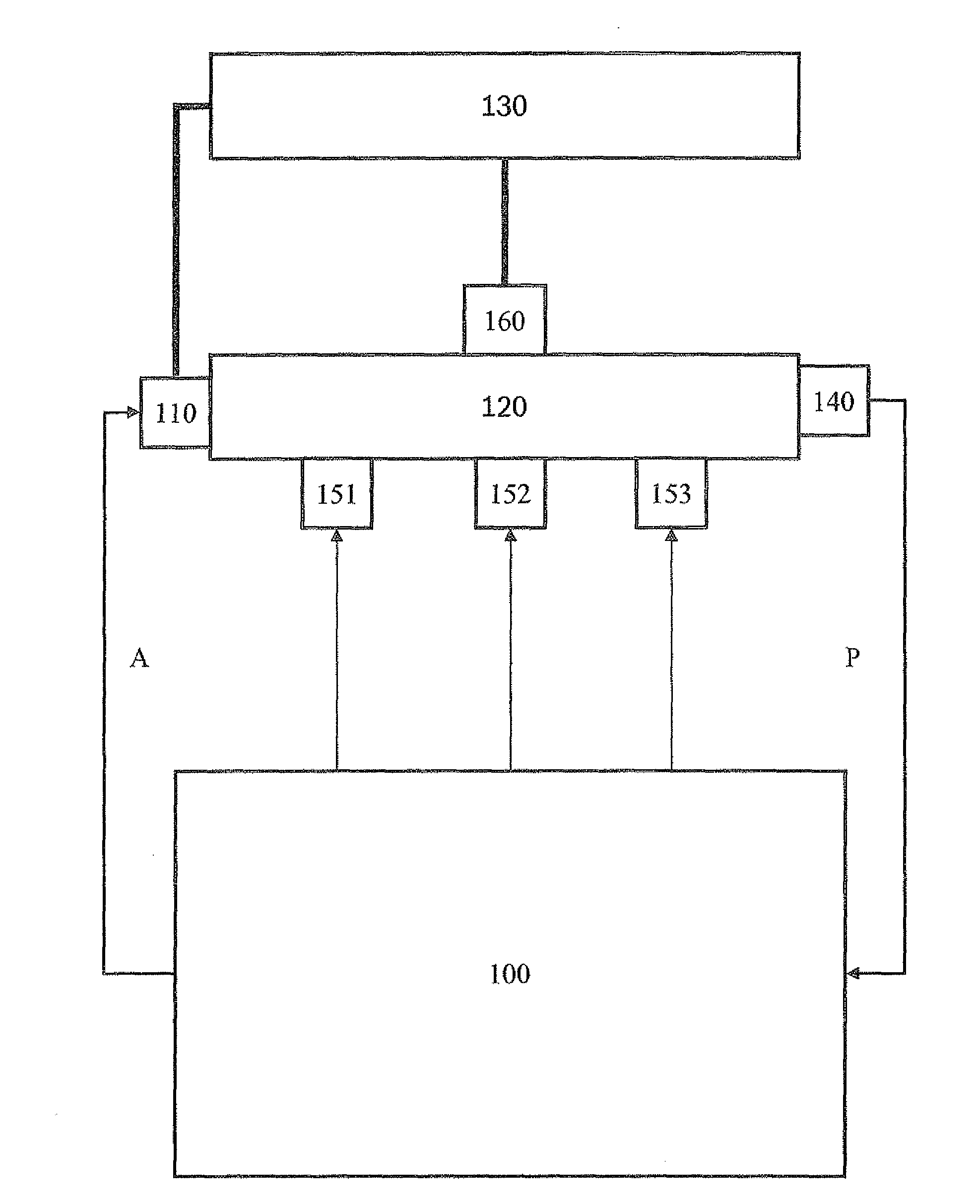
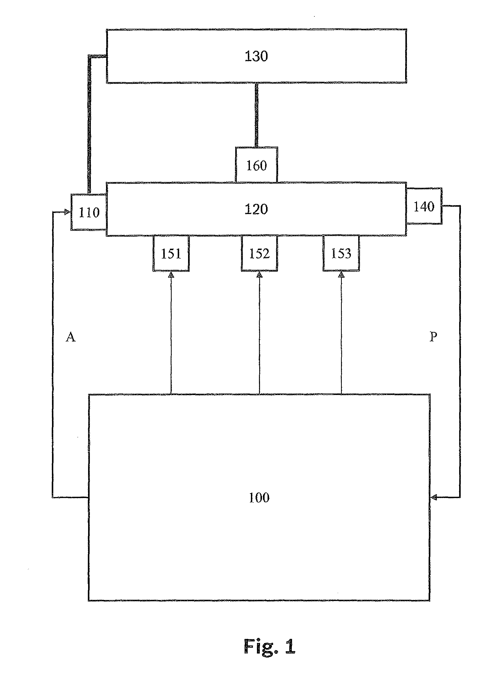
[0019]FIG. 1 shows the essential elements of a fuel metering system in the form of a block diagram. A control unit is labeled as 100. It controls an actuator 110 for controlling fuel pressure P via a triggering signal A. The exemplary embodiment shown here is a so-called pressure regulating valve, connecting a high-pressure area 120 to a low-pressure area 130. Furthermore, actuator 110 may be designed as a controllable high-pressure pump. In this case, the high-pressure pump delivers fuel from low-pressure area 130 to high-pressure area 120. The quantity delivered and thus the pressure in the high-pressure area may be controlled through appropriate triggering of an electromagnetic valve.

[0020]A sensor 140 detects the instantaneous value of the pressure in the high-pressure area which is also referred to below as rail pressure P. Sensor 140 is also referred to below as the rail pressure sensor. An appropriate signal of sensor 140 goes to control unit 100. Depending on the various add...


PUM


Abstract

A method and a device for controlling a fuel metering system are described. The fuel metering system includes at least one injector for injecting fuel into an internal combustion engine. An electric current value is applied to the at least one injector, and a rail pressure value is determined based on the electric current value.

Description

FIELD OF THE INVENTION[0001]The present invention is directed to a device and a method for controlling a fuel metering system.BACKGROUND INFORMATION[0002]German patent document DE 196 26 689 discusses a method and a device for monitoring an injection system. It discusses a so-called common rail system, in which at least one injector injects fuel from a high-pressure area into a combustion chamber of an internal combustion engine. The pressure in the high-pressure area is controllable via at least one actuator. In addition, a sensor via which the pressure in the high-pressure area is detected is usually provided. The pressure in the high-pressure area is detected against the background of the rail pressure, as the pressure in the high-pressure area is also referred to, being regulated at a predefined level. Furthermore, the rail pressure is required to implement an accurate metering of fuel.[0003]In the event of a failure of this rail pressure sensor, suitable measures must usually b...

Claims


Application Information

Patent Timeline
Patent Type & Authority Applications(United States)
IPC IPC(8): G01M15/09G01R19/00
CPCF02D41/20F02D41/222F02D41/3863F02D2200/0604F02D2041/223F02D2041/227F02D2041/2058
Inventor HERMES, HENNINGDEGLER, TRAUGOTTHEMPEL, ANDREASSOMMERER, ANDREASNAGLER, JENS-UWEMARHEINEKE, MARCUS
Owner ROBERT BOSCH GMBH
Why Eureka
Try Eureka