
Insulating compositions and devices incorporating the same

a technology of compositions and components, applied in the field of insulation compositions, can solve the problems of affecting the performance of conventional insulation, difficult to predict the overall insulation performance, and a large tendency to discharge partial discharges, and achieve the effect of increasing strength

Inactive Publication Date: 2011-01-27
GENERAL ELECTRIC CO
View PDF18 Cites 8 Cited by
  • Summary
  • Abstract
  • Description
  • Claims
  • Application Information

AI Technical Summary

Benefits of technology

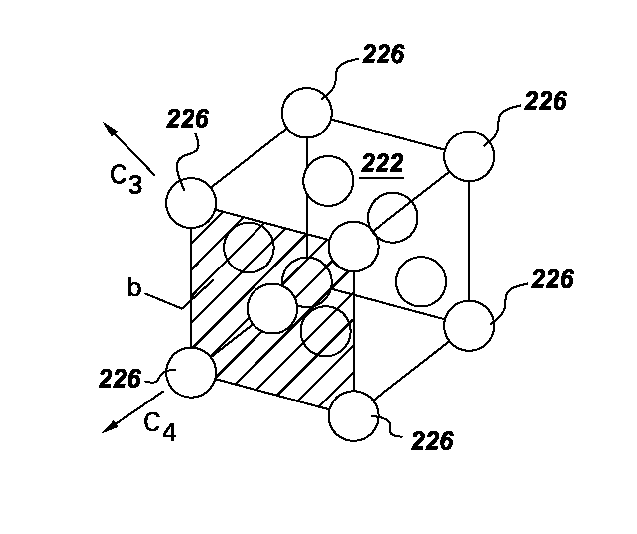
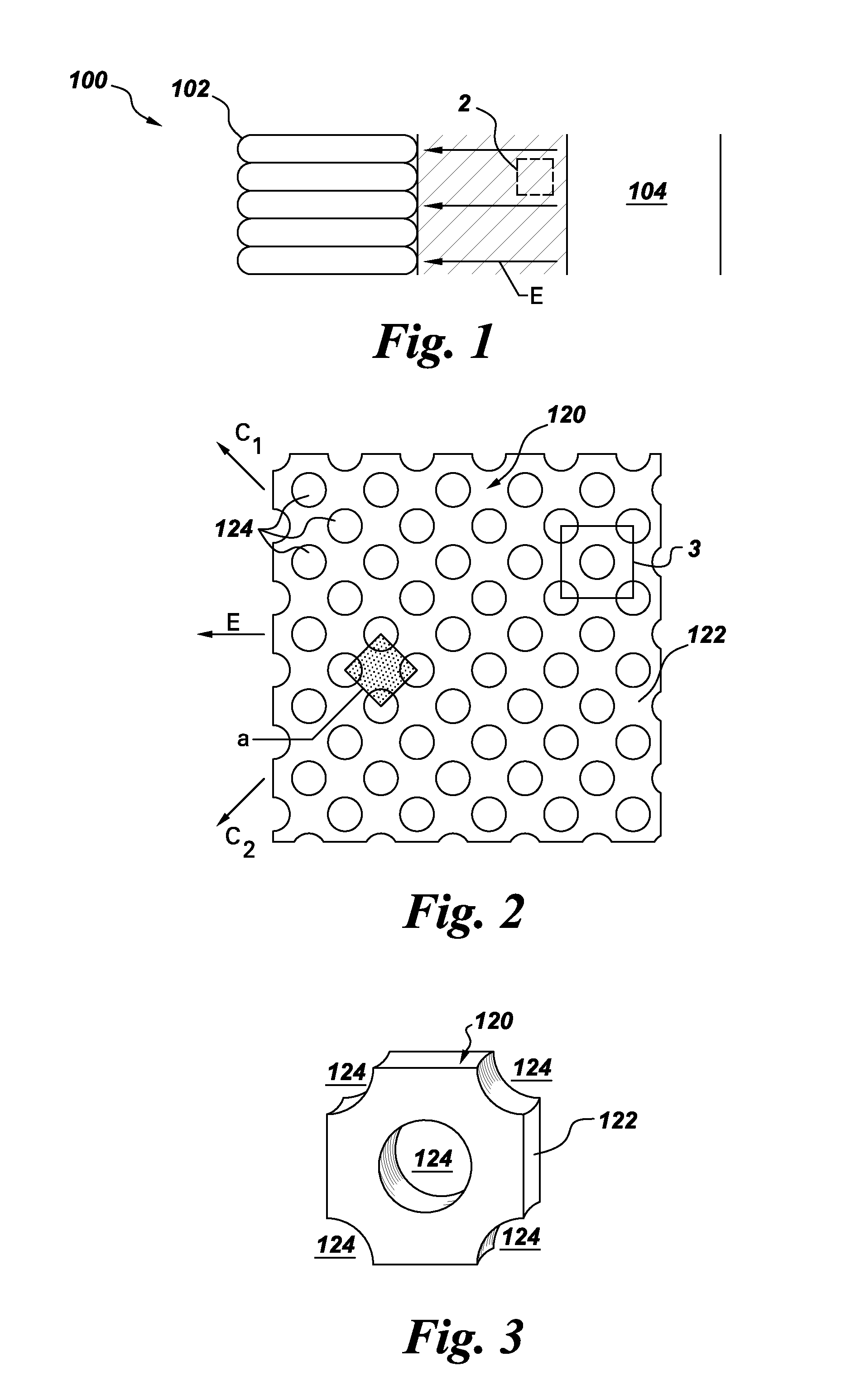
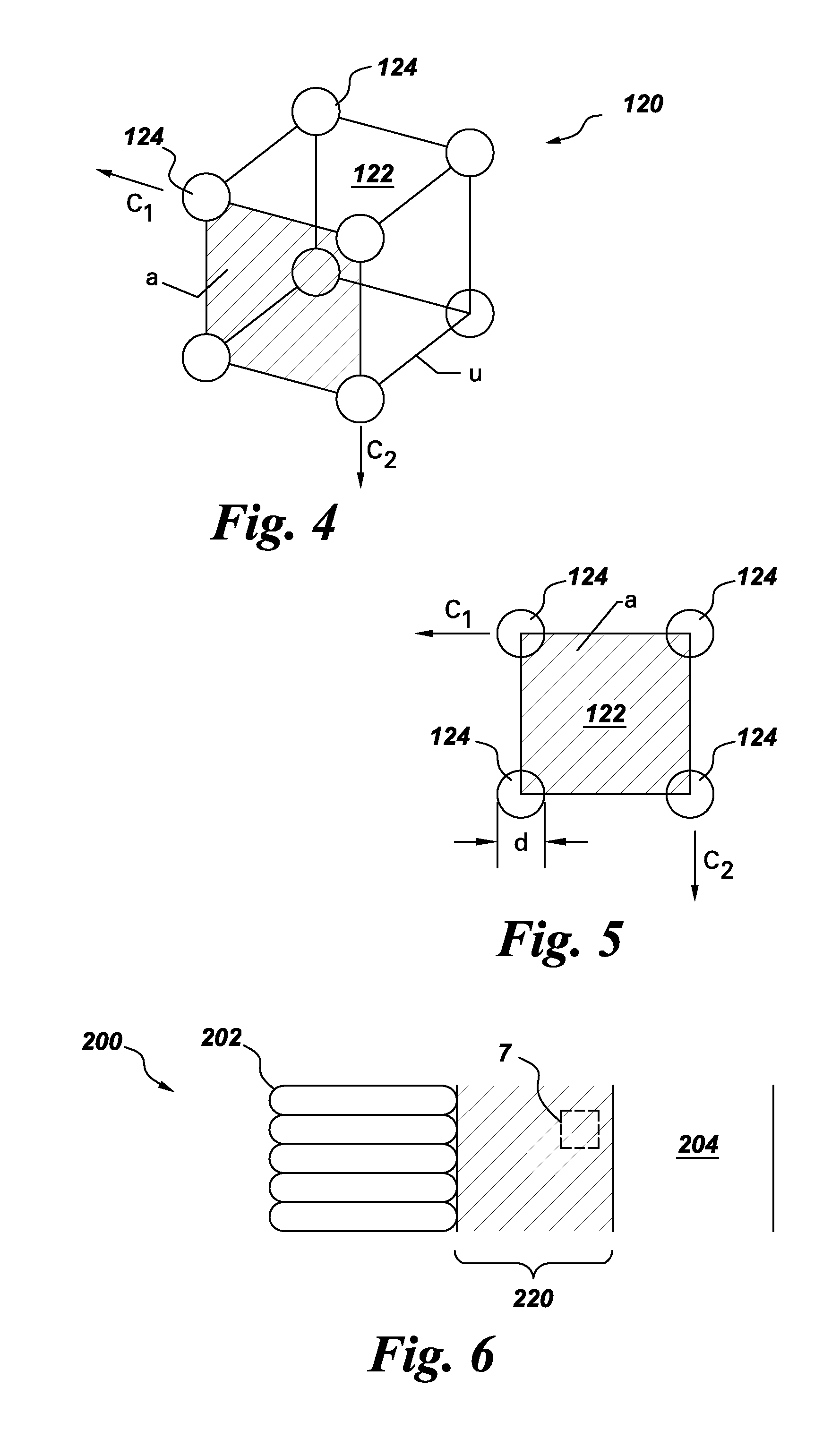
"The patent describes a composition that includes a matrix material with multiple voids that are arranged in a uniform pattern. These voids can contain hollow particles or other particles that can interact with charges in the voids to cause movement of the charges in a direction transverse to an electric field. The spacing between the voids is small, and the composition can be used in high voltage devices. The technical effect of this invention is to provide a new material that can be used in high voltage devices to insulate and protect components from electrical arcing."

Problems solved by technology

As such, conventional insulation tends to be a complicated system.
Further, each of the constituent components is expected to exhibit different electrical, thermal, and mechanical properties, making overall insulation performance difficult to predict.
Partial discharges largely tend to occur at structural defects such as voids, delaminations, and cracks in the insulation.
The lower dielectric constant leads to a higher impedance and voltage in the localized defect region, and hence leads to partial discharges.
Consequences of such partial discharges include changes in the chemistry due to oxidation or carbonization and subsequently treeing, cracking, and eventual catastrophic failure of the insulation.

Method used


Image

  • Insulating compositions and devices incorporating the same
  • Insulating compositions and devices incorporating the same
  • Insulating compositions and devices incorporating the same

Examples


Embodiment Construction

[0023]Example embodiments of the present invention are described below in detail with reference to the accompanying drawings, where the same reference numerals denote the same parts throughout the drawings. Some of these embodiments may address some of the above and other needs.

[0024]Referring to FIG. 1, therein is shown a portion of an electrical system 100 configured in accordance with an example embodiment. The system 100 can include a first conductive component, such as a phase conductor 102, and a second conductive component, such as a ground conductor 104. The phase conductor 102 can connect to a high voltage supply. During operation of the generator 100, the phase conductor 102 and the ground conductor 104 can be maintained at different potentials. For example, the phase conductor 102 may be held at a high voltage through the operation of the excitation source, while the ground conductor 104 may be held at ground potential. As such, an electric field E may be established betw...


PUM

PropertyMeasurementUnit
diametersaaaaaaaaaa
diameteraaaaaaaaaa
diametersaaaaaaaaaa

Abstract

Provided are compositions that include a dielectric matrix material defining multiple voids of substantially uniform respective dimension and configured as a substantially uniform array. The voids may be configured such that charges that accumulate at surfaces of at least some of the voids when the composition is immersed in a uniform external electric field interact with charges that accumulate at surfaces of at least others of the voids to cause movement of the respective charges in a direction having a component transverse to the electric field. Hollow particles may be disposed within respective voids of the array of voids defined by the matrix material, and particles, such as, for example, ceramic, varistor, and / or inorganic dielectric particles, may be incorporated within the matrix material. Associated devices are also provided.

Description

BACKGROUND[0001]The invention relates generally to insulating compositions, and in particular to insulating compositions for use in high voltage devices.[0002]Conventional insulation used in products such as motors and generators typically include several components, such as enamel, tapes, and resin. As such, conventional insulation tends to be a complicated system. Further, each of the constituent components is expected to exhibit different electrical, thermal, and mechanical properties, making overall insulation performance difficult to predict.[0003]One of the major performance parameters is being monitored is the partial discharge magnitude. Partial discharges largely tend to occur at structural defects such as voids, delaminations, and cracks in the insulation. The partial discharges in these defects are caused by the lower dielectric constant at the defects due to the presence of air, compared to that of the surrounding solid insulation materials. The lower dielectric constant...

Claims


Application Information

Patent Timeline
Patent Type & Authority Applications(United States)
IPC IPC(8): H01B3/00B32B3/26H01B3/30C08K3/22
CPCH02K3/40H02K3/30Y10T428/249971Y10T428/249921Y10T428/249972Y10T428/249974
Inventor ASOKAN, THANGAVELUDAS, SUBHANKARBOHORI, ADNAN KUTUBUDDIN
Owner GENERAL ELECTRIC CO
Learn More