Single Inductor Serial-Parallel LED Driver

a technology of led driver and serial parallelization, which is applied in the direction of electroluminescent light source, lighting apparatus, light source, etc., can solve the problems of reduced life, failure in operation, and overall quality of display images, and achieve the effect of increasing the tolerance of the overall system to led mismatch due to manufacturing processes

Inactive Publication Date: 2011-01-27
AVAGO TECH WIRELESS IP SINGAPORE PTE
View PDF7 Cites 11 Cited by
  • Summary
  • Abstract
  • Description
  • Claims
  • Application Information

AI Technical Summary

Benefits of technology

[0016]The LED driver includes a voltage control loop that dynamically regulates the output voltage across the parallel arrangement of LED strings. The output voltage is dynamically adjusted to accommodate the LED string with the largest operational voltage drop, which allows for LED strings with different voltage drops to be powered in an efficient manner. Further, each LED string also includes an individual current regulation loop so that the current, and therefore optical brightness, of each LED string can be individually adjusted.
[0017]As discussed, the mechanism of voltage regulation ensures that the output voltage is boosted to a high enough value for all of the LED strings to operate properly. Further, this ensures that all the parallel LED strings have enough headroom available for proper current regulation. Since each LED string has its own current regulation loop, it allows for tight and precise current matching across all LED strings, if desired. In addition, the current in each LED string can be independently programmed and each LED string can be independently enabled or disabled. Furthermore, due to an additional degree of design freedom obtained by providing each LED string with its own current regulation mechanism, each LED string can have a different LED type from the others. Even further, the individual LEDs of a particular string could be different from each other as well. For example, some of the LEDs could be Flash LEDs while others could be regular LEDs. Additionally, for the same reason, the tolerance of the overall system to LED mismatch due to manufacturing processes also increases.

Problems solved by technology

Since multiple LEDs are in use in display systems, such a variation in the optical output of the LEDs leads to a degradation in the overall quality of the display images and may lead to failure in operation due to reduction in the life of an LED.
Boosting from such low input voltages to 30 Volts is not very efficient and not feasible since the duty cycle required for such a process approaches 100%.
Such a current mismatch again leads to a degradation in the output of the display.
In other words, the LED driver 200 does not have any method to regulate the current in the individual LED strings, and thus falls short of attaining maximum optical output efficiency of the display system.
Additionally, the LED driver 200 is not power efficient.
However, if one of the LED strings only requires 3 volts / per LED for a total of 12 Volts, then the extra 4 Volts is dissipated across one of the resistors 216a-n, which is an efficiency loss of 25% (4 Volts / 16 Volts*100).

Method used


Image

  • Single Inductor Serial-Parallel LED Driver
  • Single Inductor Serial-Parallel LED Driver
  • Single Inductor Serial-Parallel LED Driver

Examples


Embodiment Construction

[0025]An LED driver circuit is disclosed for an LED display system that includes the ability to control the current in each LED string and the voltage output. The present invention also provides improved power efficiency and scalability. In the following description, specific details are set forth in order to provide a thorough understanding of the present invention. It will be understood, however, to one skilled in the art, that the present invention may be practiced without some or all of these specific details. In other instances, well known process operations have not been described in detail, as they are well known to those skilled in the art.

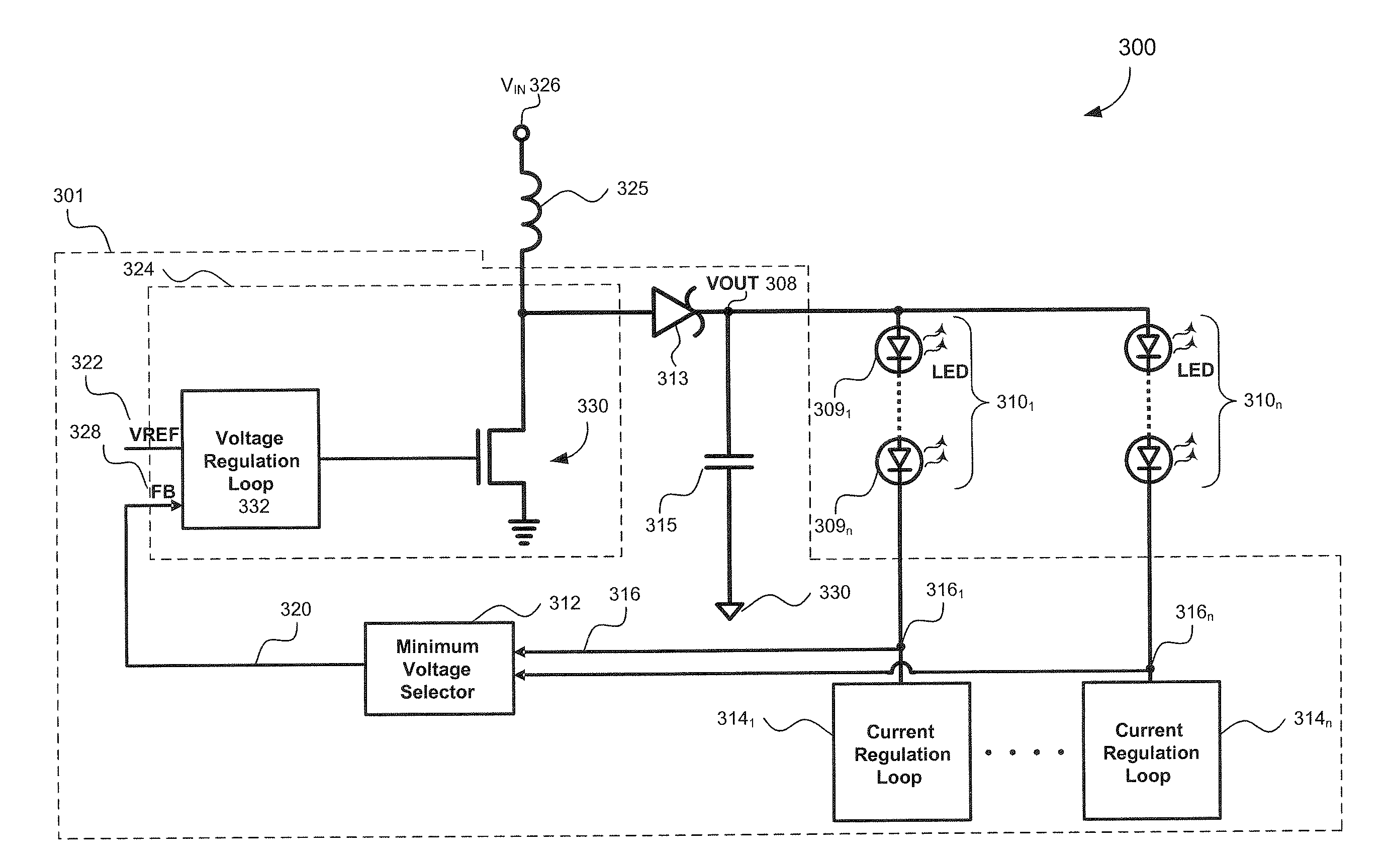
[0026]FIG. 3 illustrates a LED display system 300 having an LED driver 301 driving a plurality LED strings 3101 to 310n according to embodiments of the invention, where each LED string 310 includes a plurality of LEDs 309. As shown, the LED strings 3101 to 310n are connected in parallel with each other, but the LEDs 309 in each LED string ...


PUM


Abstract

An LED driver circuit is disclosed that can drive a plurality of LED strings that are arranged in parallel, each LED string having a plurality of component LEDs that are series-connected. The LED strings can be the same type of LEDs in each string, or have different types of LEDs from one string to another. The LED driver includes a voltage control loop that dynamically regulates the output voltage across the parallel arrangement of LED strings. The output voltage is dynamically adjusted to accommodate the LED string with the largest operational voltage drop. This enables LED displays to constructed using different types of LEDs strings, but still supply the LED strings in a power efficient manner. Further, each LED string also includes its own individual current regulation loop so that the current, and therefore brightness, of each LED string can be individually adjusted.

Description

CROSS REFERENCE TO RELATED APPLICATIONS[0001]This application is a continuation of U.S. patent application Ser. No. 11 / 790,221, filed on Apr. 24, 2007, now allowed, titled “Single Inductor Serial-Parallel LED Driver”, which claims the benefit of U.S. Provisional Application No. 60 / 841,543, filed on Sep. 1, 2006, which is incorporated by reference herein in its entirety.BACKGROUND OF THE INVENTION[0002]1. Field of the Invention[0003]The present invention is directed to a driver circuit for a Light Emitting Diode (LED) display system that can be used, for example, in cellular phones, PDAs, and other similar visual display units. More particularly, this invention is directed to providing driver circuitry to drive a multi-string configuration of different types of LEDs used in display systems.[0004]2. Background Art[0005]Modern day display systems increasingly rely upon LEDs to render a high quality visual display. The applications can include displays for cell phones, personal digital ...

Claims


Application Information

Patent Timeline
Patent Type & Authority Applications(United States)
IPC IPC(8): H05B37/02
CPCH05B33/0815Y02B20/347H05B33/0827H05B45/38H05B45/46Y02B20/30
Inventor KOTIKALAPOODI, SRIDHAR V.ZENG, JAMESSZABO, TIVADARPANDYN, MANISHA P.ROOHPARVAR, FARZAN
Owner AVAGO TECH WIRELESS IP SINGAPORE PTE
Why Eureka
Try Eureka