Ultrasound zone location system with high capacity

a high-capacity, ultrasonic technology, applied in the direction of ultrasonic/sonic/infrasonic wave beacon systems, instruments, sensing details, etc., can solve the problems of ir sensing vulnerability, less suited rf signals, and rather few rf stations, so as to achieve high location precision, low power consumption, and reliable operation with rather few components

Active Publication Date: 2011-01-27
UNIVERSITY OF OSLO
View PDF78 Cites 55 Cited by
  • Summary
  • Abstract
  • Description
  • Claims
  • Application Information

AI Technical Summary

Benefits of technology

[0013]Thus, according to the above description, it is an object of the present invention to provide a simple zone location system which is capable of functioning reliably with r

Problems solved by technology

Such systems only require rather few RF stations, since RF signals can cover a large area, since such signals easily penetrate building elements etc.
However, for zone location applications, RF signals are less suited, since the geometric position of the portable tag must be determined rather precisely e.g. to be able to determine in which of two neighbouring rooms the portable tag is present.
However, in practice IR sensing is vulnerable and requires many sensors to cover one zone, since IR signal communication is easily hindered if there is not a clear line-of-sight between transmitter and receiver, e.g. a thin curtain may be provide enough obstacle effect to destroy IR communication.
Further, location systems based on US signals have a rather poor capacity.
This is due to the fact that US signals travel at the speed of sound which is much slower than RF waves, and further, the bandwidth of US waves is limited compared to RF sig

Method used


Image

  • Ultrasound zone location system with high capacity
  • Ultrasound zone location system with high capacity
  • Ultrasound zone location system with high capacity

Examples


Embodiment Construction

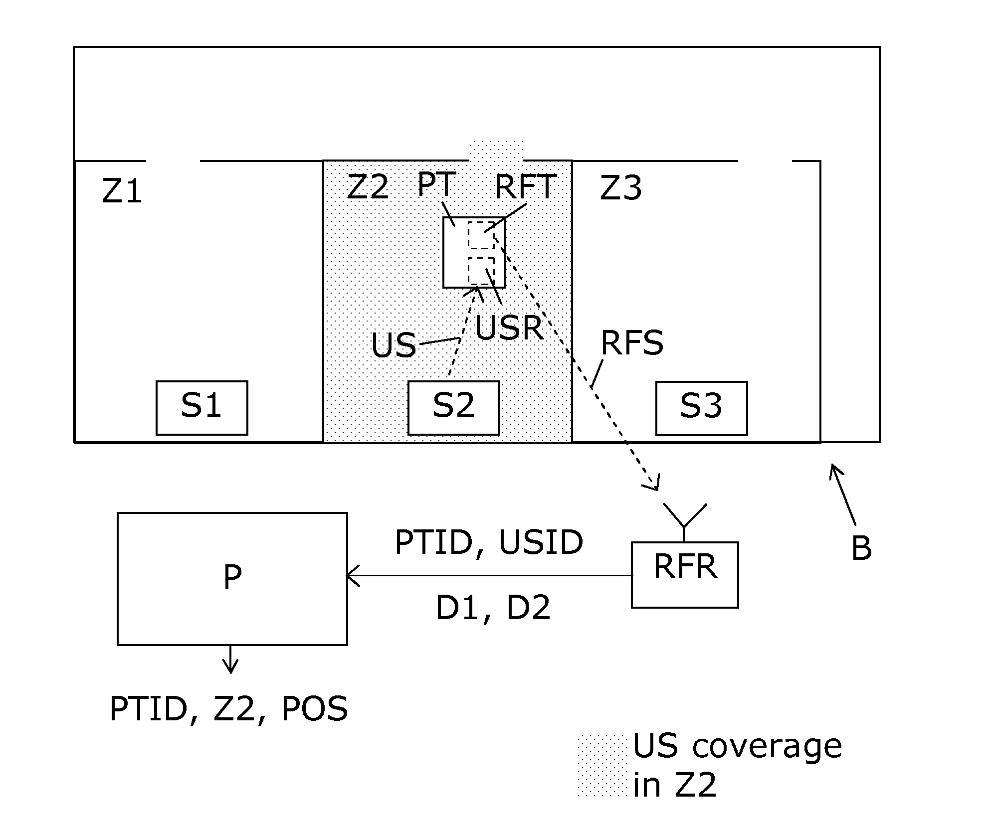
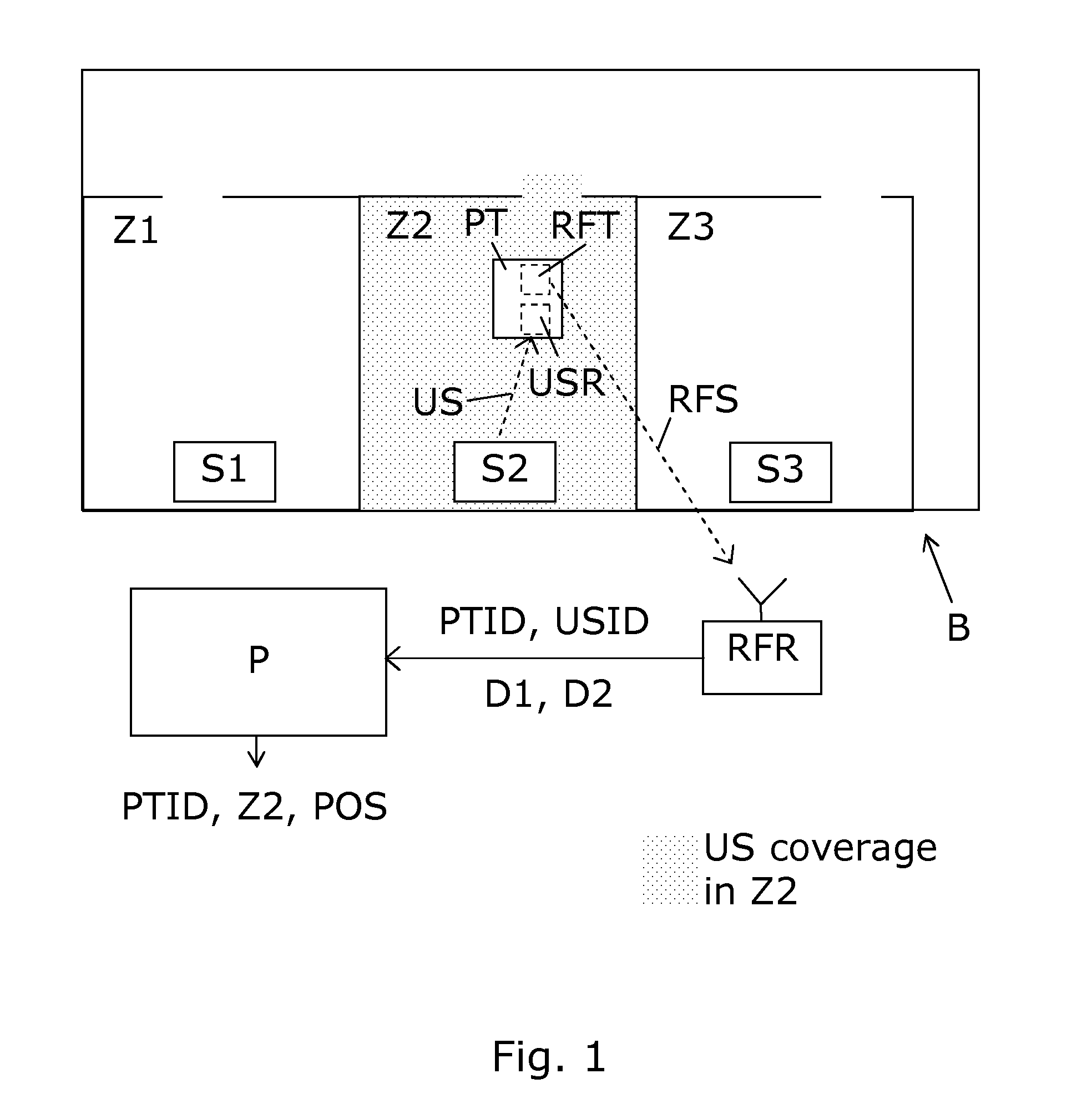
[0061]FIG. 1 shows an overall sketch serving to illustrate basic components of a rather simple embodiment of the zone location system according to the invention. A portable tag PT includes an RF transmitter RFT and a US receiver. The shown embodiment is arranged to locate in which of the zones Z1, Z2, Z3 the portable tag PT is present, the zones Z1, Z2, Z3 corresponding to rooms of a building B. US transmitters 51, S2, S3 are installed in the respective zones Z1, Z2, Z3 and transmit US signals indicated as ‘US’, and this US signal includes an ID code USID identifying the US transmitter. In the illustrated example, only US transmitter S2 is capable of providing US communication with the portable tag PT, and thus the portable tag PT receives the US signal US from the US transmitter S2 and its ID code USID. The portable tag PT transmits from its RF transmitter RFT an RF signal RFS with the USID and its own ID code PTID. Further the RF signal RFS includes first and second data values D1...


PUM


Abstract

A zone location system with ultrasound US transmitters S1, S2, S3 located in respective zones Z1, Z2, Z3 such as rooms of a building B. Preferably, the US transmitters are time-multiplexed so that each of them in turn transmits a US signal US with a unique ID code USID represented therein. The portable tag PT includes an ultrasound receiver USR arranged to receive the US signal. Based on the received US signal, the portable tag PT measures a strength of the received US signal. The portable tag PT also measures a parameter related to a movement of the portable tag PT, e.g. a Doppler shift based on the received US signal. Further, the portable tag extracts the USID. Then it transmits a wireless Radio Frequency signal RFS with its own ID PTID, the USID and first and second data values D1, D2 representing the signal strength and the movement related parameters. A processor P connected to a Radio Frequency receiver RFR receives the data from the portable tag PT and determines a connection between PTID and the zone Z2 in which it is present based on the USID. Further, the processor utilizes data D1 and D2 to calculate an estimated position POS within the zone Z2. Especially, estimated distance between US transmitter S2 and portable tag PT and velocity of the portable tag may be estimated based on D1 and D2, thus assisting in estimating the position POS of the portable tag PT. The system may further be combined with a Radio Frequency based positioning system, e.g. an RF signal strength based system, thereby enhancing the resolution of the estimated position POS of the portable tag PT. Further, such combined system help location in complicated and changing environments and in situations where the portable tag PT may be out of reach for US signals, e.g. when attached to a paper file enclosed in a box.

Description

FIELD OF THE INVENTION[0001]The present invention relates to the field of positioning or location systems, especially the invention related to the field of ultrasound-based zone location systems. More specifically, the invention provides a high capacity ultrasound zone location system assisted by radio frequency communication.BACKGROUND OF THE INVENTION[0002]A large variety of positioning or location systems capable of tracking persons or mobile objects in real-time, e.g. within a work place or a factory exist. Such systems determine a position of a portable tag attached to the person or object by establishing a communication between the portable tag and one or more stationary US stations. Many different methods and types of signals have been suggested for such systems.[0003]Radio Frequency (RF) signals can be used to determine the position of the portable tag, e.g. by calculating the geometric position of the portable tag based on triangulation, i.e. based on sensing phase differen...

Claims


Application Information

Patent Timeline
IPC IPC(8): G06K7/01
CPCG01S1/72G01S11/14
Inventor HOLM, SVERRE
Owner UNIVERSITY OF OSLO
Why Eureka
Try Eureka