Image displaying apparatus and optical Apparatus

Inactive Publication Date: 2011-01-27
SONY CORP
View PDF5 Cites 134 Cited by
  • Summary
  • Abstract
  • Description
  • Claims
  • Application Information

AI Technical Summary

Benefits of technology

0078] In the image displaying apparatus and the optical apparatus according to the first mode of the present invention, the first light conduction section is disposed between the image production apparatus and the second light conduction section and is configured from the first light conduction plate and the reflection type volume hologram diffraction grating. Accordingly, the first light conduction section functions as a kind of beam expander, that is, as a kind of beam expansion means, and the shape of a light flux emitted from the image production apparatus and introduced into the first light conduction section is expanded along the light propagation direction by the internal total reflection in the first light conduction plate by the reflection type volume hologram diffraction grating. Then, the light flux of the expanded form is introduced into the second light conduction section. On the other hand, the image displaying apparatus and the optical apparatus according to the second mode of the present invention include

Problems solved by technology

On the other hand, with such a configuration as described above, since the propagation distance of the light cond

Method used


Image

  • Image displaying apparatus and optical Apparatus
  • Image displaying apparatus and optical Apparatus
  • Image displaying apparatus and optical Apparatus

Examples


embodiment 1

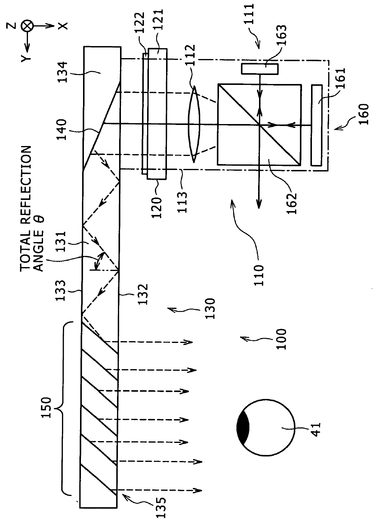
[0172] An embodiment 1 relates to the image displaying apparatus according to the first mode of the present invention and the optical apparatus according to the first mode of the present invention and further relates to the image production apparatus of the first form. The image displaying apparatus according to the embodiment 1 and embodiments 2 to 4 hereinafter described are conceptually shown in FIGS. 1, 2, 3A and 4, respectively. Further, an arrangement state of the image production apparatus, a first light conduction section and a second light conduction section is schematically shown in FIG. 5A, and a concept when the first light conduction section is cut is illustrated in FIG. 5B.

[0173] The image displaying apparatus 100, 200, 300 or 400 according to the embodiment 1 or any of the embodiments 2 to 4 hereinafter described includes

[0174] (A) an image production apparatus 110 or 210;

[0175] (B) a first light conduction section 120 adapted to receive, conduct and emit the light em...

embodiment 2

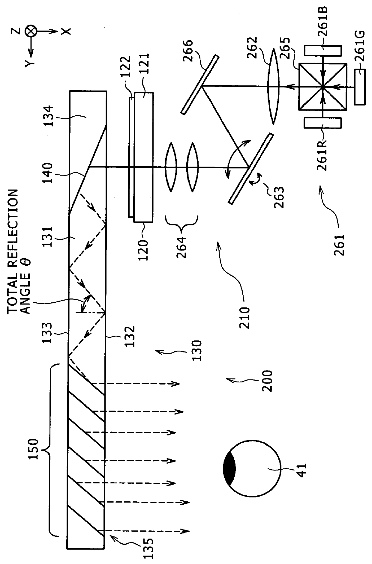
[0205] The embodiment 2 is a modification to the embodiment 1 and relates to the image production apparatus 210 of the second mode. The image displaying apparatus 200 of the embodiment 2 or an image displaying apparatus 400 of the embodiment 4 hereinafter described includes, as shown in FIG. 2 or 4,

[0206] (A-1) a light source 261;

[0207] (A-2) a collimate optical system 262 for converting light emitted from the light source 261 into parallel light;

[0208] (A-3) a scanning section 263 for scanning the parallel light emitted from the collimate optical system 262; and

[0209] (A-4) a relay optical system 264 for relaying the parallel light scanned by the scanning section 263; and

[0210] a light flux of the parallel light obtained by the conversion by the relay optical system 264 is introduced to the first light conduction section 120.

[0211] The first light conduction section 120 and the second light conduction section 130 have a configuration and a structure similar to those of the first li...

embodiment 3

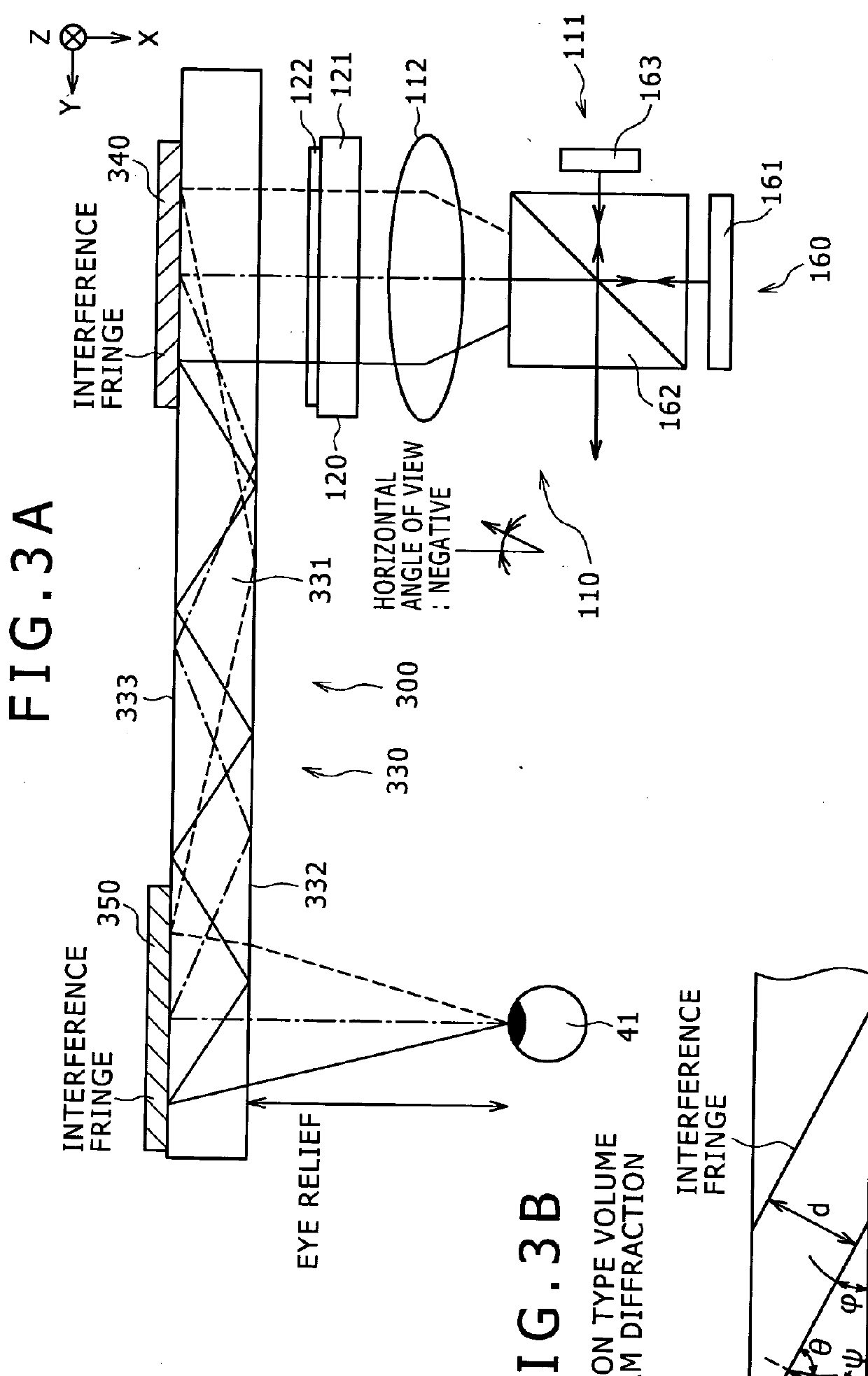
[0213] Also the embodiment 3 is a modification to the embodiment 1. Referring to FIG. 3A, the image formation apparatus 111 and collimate optical system 112 and the first light conduction section 120 in the image displaying apparatus 300 of the embodiment 3 have a configuration and a structure same as those of the image formation apparatus 111 and collimate optical system 112 and the first light conduction section 120 described hereinabove in connection with the embodiment 1, respectively. Although the second light conduction section 330 is different in the configuration and structure of the first and second deflection sections, also it has a basic configuration and structure similar to those of the second light conduction section 130 in the embodiment 1. In particular, the second light conduction section 330 includes

[0214] (C-1) a second light conduction plate 331 adapted to propagate incoming light in the inside thereof by total reflection and then emit the light;

[0215] (C-2) a fi...


PUM


Abstract

The image displaying apparatus includes an image production apparatus, a first light conduction section and a second light conduction section. The first light conduction section includes a first light conduction plate which propagates part of incident light thereto by total reflection in the inside thereof and emits the propagated light, and a reflection type volume hologram diffraction grating disposed on the first light conduction plate. The second light conduction section includes a second light conduction plate, a first deflection section and a second deflection section.

Description

BACKGROUND OF THE INVENTION[0001] 1. Field of the Invention[0002] This invention relates to an optical apparatus and an image displaying apparatus in which the optical apparatus is incorporated.[0003] 2. Description of the Related Art[0004] A virtual image displaying apparatus as an image displaying apparatus wherein a virtual image optical system allows a two-dimensional image formed by an image formation apparatus to be observed as an enlarged virtual image by an observer is well known, for example, from JP-T-2005-521099 and Japanese Patent Laid-Open No. 2006-162767.[0005] As conceptually illustrated in FIG. 25, the image displaying apparatus 900 mentioned includes an image formation apparatus 911 including a plurality of pixels arranged in a two-dimensional matrix, a collimate optical system 912 for converting light emitted from the pixels of the image formation apparatus 911 into parallel light and a light conduction section 930 for receiving, conducting and emitting the paralle...

Claims


Application Information

Patent Timeline
IPC IPC(8): G02B27/01G02B5/32
CPCG02B5/32G02B6/00G02B2027/0174G02B2027/0125G02B27/0172G02B5/1828G02B6/0038
Inventor AIKI, KAZUMAAKUTSU, KATSUYUKI
Owner SONY CORP
Why Eureka
Try Eureka