Method and illumination device for optical contrast enhancement

a technology of illumination device and optical contrast, which is applied in image enhancement, television system, instruments, etc., can solve the problems of relatively low light throughput, short service life of illumination device, and inability to directly display hdr images

Inactive Publication Date: 2011-01-27
BAUHAUS UNIVERSITY
View PDF13 Cites 47 Cited by
  • Summary
  • Abstract
  • Description
  • Claims
  • Application Information

AI Technical Summary

Benefits of technology

[0046]In another embodiment of the method, image parameters for selecting at least one image segment of the reproduction of the object are determined. Through regulation of the illumination characteristics of the at least one light projection unit, at least one area of the object corresponding to at least one ascertained image segment is emphasized or masked by a local alteration of the illumination intensity and/or illumination color.
[0047]In this context, an area that is said to be masked is not illuminated or is illuminated significantly less strongly in comparison with other areas.
[0048]By means of emphasis, an especially interesting area of the object can advantageously be visually highlighted, so that a viewer of the reproduction of this object is directed to this area. By means of masking, non-relevant areas of the object can be hidden, and the viewer's attention can advantageously be drawn to the important areas of the object. For example, such emphasis or masking can be used advantageously in assistance systems in surgical operations in order to concentrate the choice of images on the areas of the object that are relevant for a particular

Problems solved by technology

To date, however, only few output devices exist that are capable of directly displaying HDR images.
All the approaches known from the above-mentioned publications are beset by the following disadvantages: Firstly, they use a transmissive image modulation (either through transparencies or LCD/LCoS panels, LCoS=Liquid Crystal on Silicon), consequently suffer from a relatively low light throughput and ther

Method used


Image

  • Method and illumination device for optical contrast enhancement
  • Method and illumination device for optical contrast enhancement
  • Method and illumination device for optical contrast enhancement

Examples


first embodiment

[0080]Splitting a source image IHDR: As already described in brief above, in the inventive method the first image IA and the second image IB are obtained from a source image IHDR. This generation of the images IA, IB is also referred to below as splitting of the source image IHDR. Especially when the source image IHDR is present in the form of an HDR data record, the two images IA, IB are preferably generated from the source image IHDR in accordance with the following calculation rule:

IA=TMAB(IHDR)γaa+b,[1]IB=TMAB(IHDR)γ / TA(IA),[2]

[0081]where the following notations are used: TMAB: tone mapping operator (dynamic compression operator); TA: linearized transfer function of the image display device A; a: bit depth of the image display device A; b: bit depth of the light projection unit B; and γ: gamma correction factor.

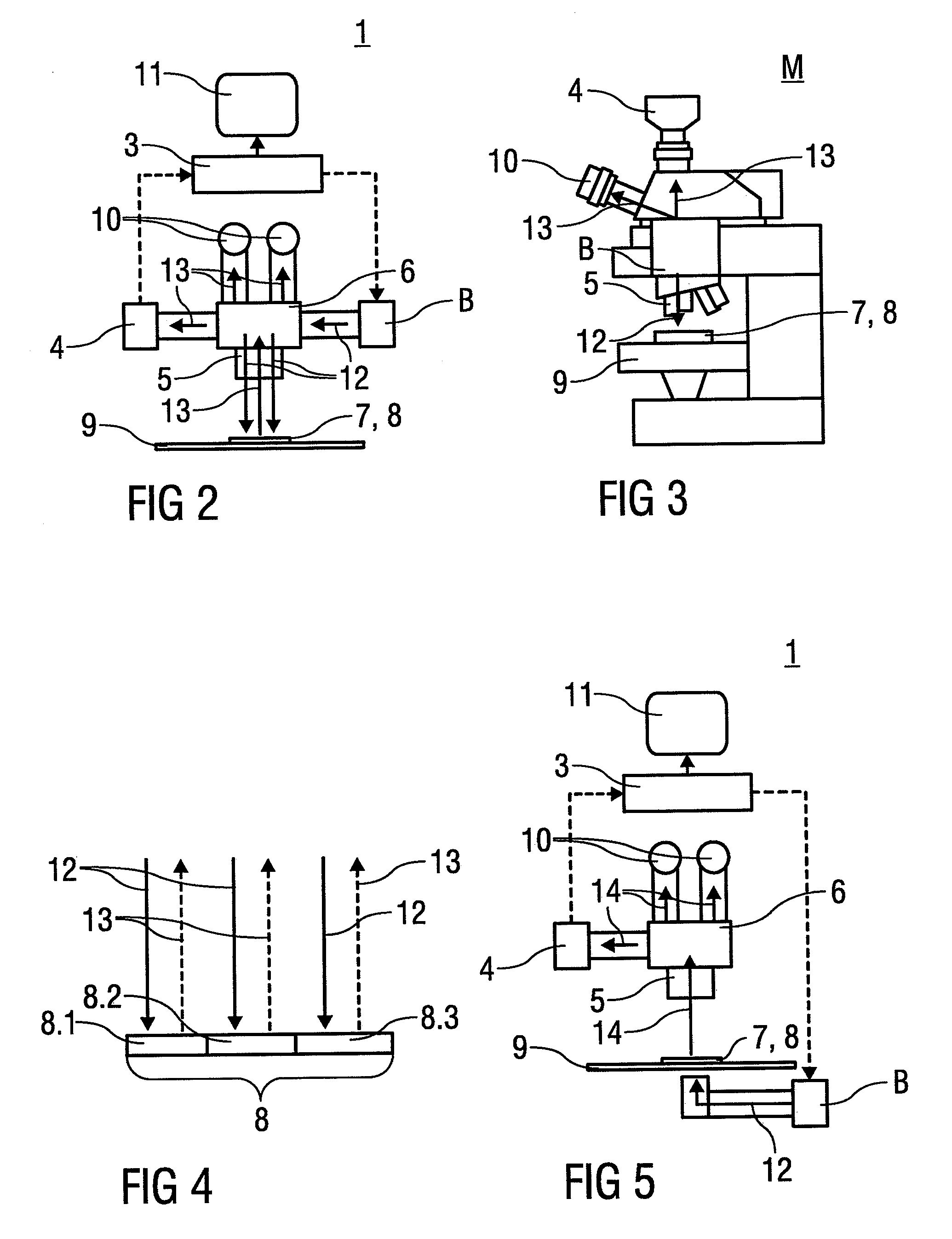
[0082]According to the invention, the first image IA is displayed by means of an image display device A, for example a printer or electronic paper, and the second image I...

second embodiment

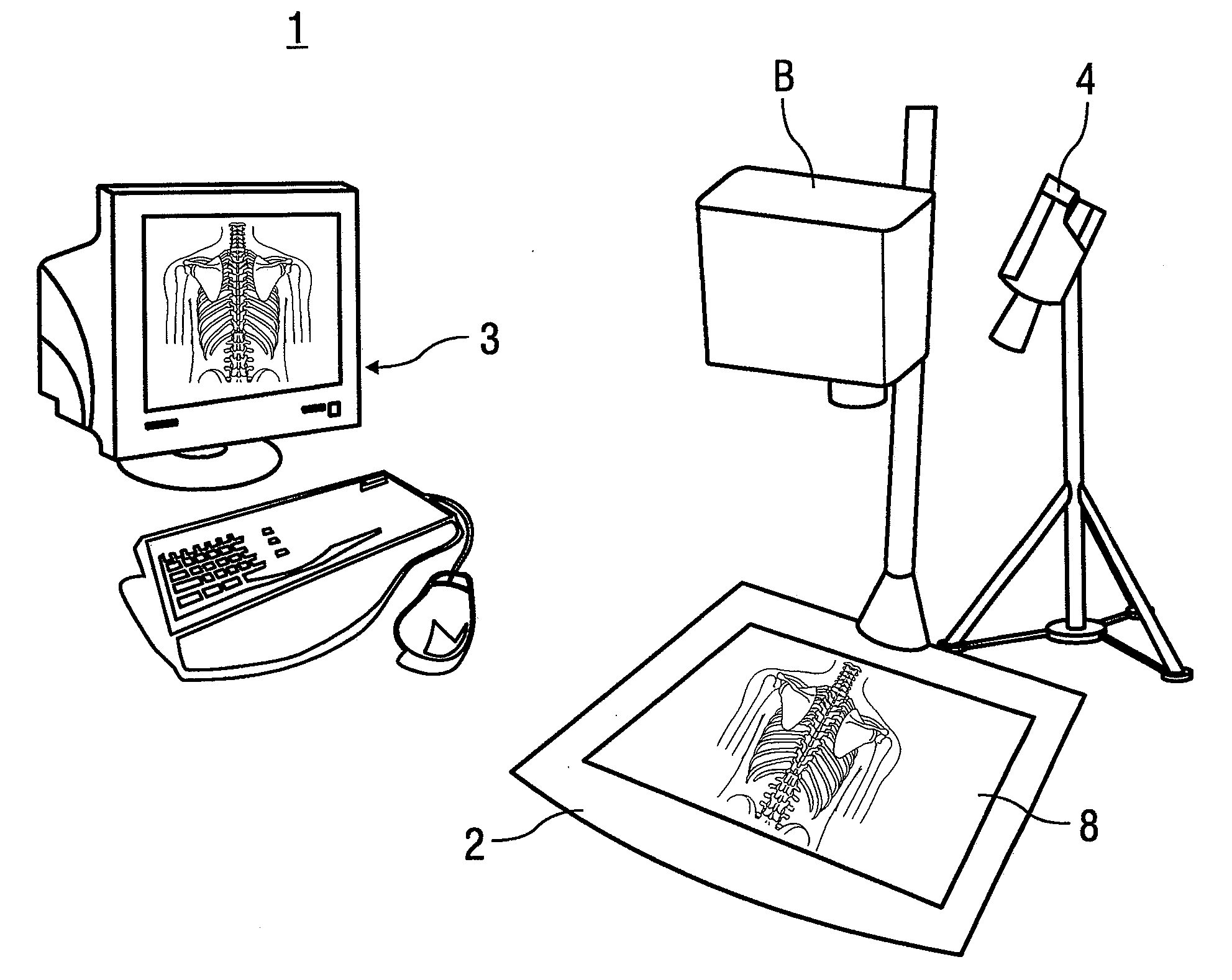
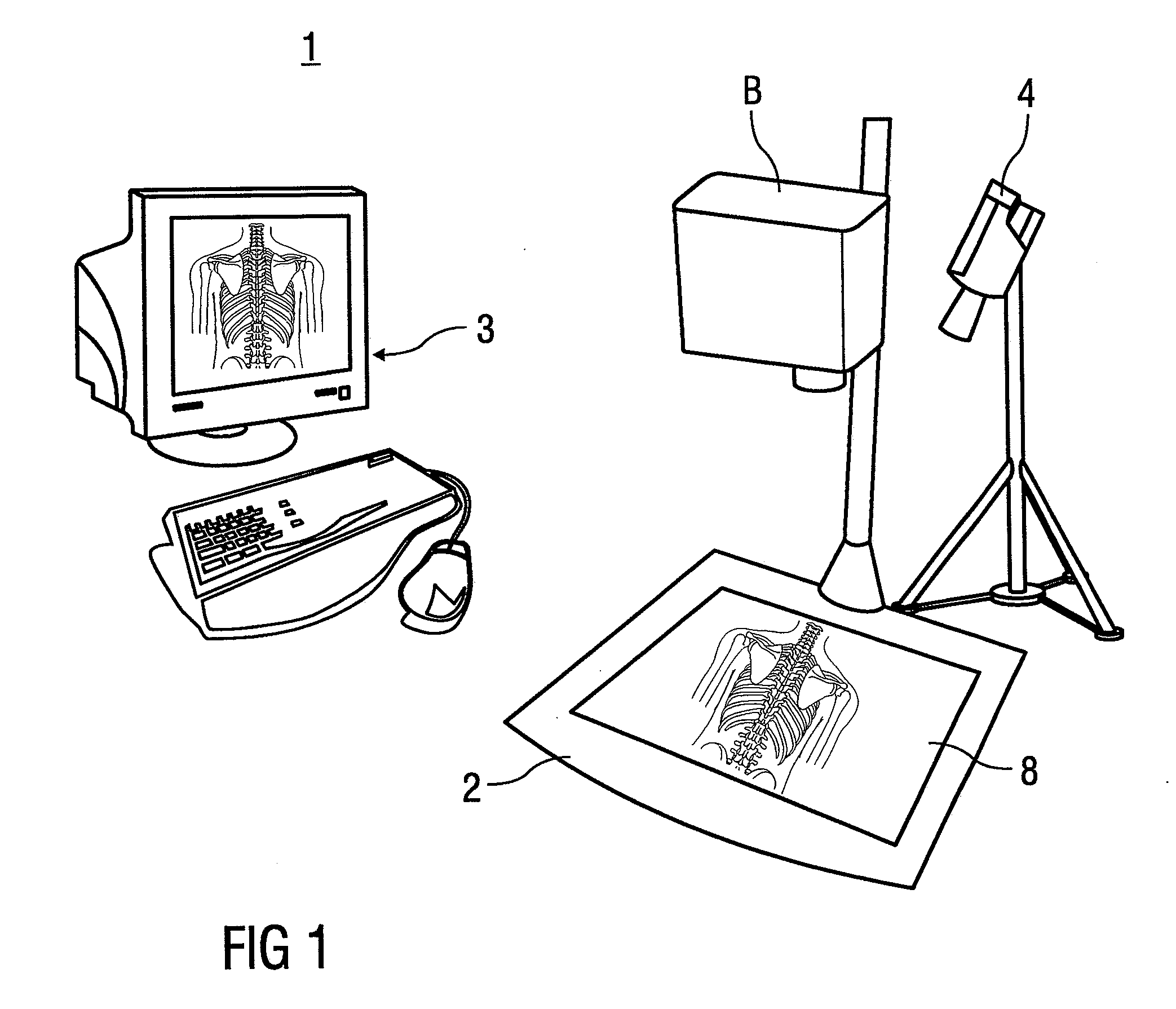
[0103]Inverse tone mapping: In the inventive method, the image data record which is used to derive the modulated illumination of the object 8 is produced from a camera image of the object 8 recorded with the camera 4, and an illumination data record for controlling the light projection unit is created from the image data record.

[0104]In this process, an intermediate image with an increased contrast ratio relative to the camera image is preferably generated first, and the illumination data record is then created from the intermediate image. An inverse tone mapping operator that was described in the aforementioned disclosure by BANTERLE et al. can be used, for example.

[0105]As already mentioned, in this case the intermediate image takes over the role of the source image IHDR, and the illumination data record takes over the role of the second image IB of the first embodiment, in the sense that an HDR-like image is created by means of the inverse tone mapping, and the illumination data ...


PUM


Abstract

A method and an illumination device is provided for optical contrast enhancement of an object through a spatially and/or temporally modulated illumination of the object by way of at least one light projection unit, wherein the spatial and/or temporal modulation of the illumination of the object is determined using a set of image data associated with the object.

Description

[0001]This nonprovisional application is a continuation of International Application No. PCT / EP2009 / 053549, which was filed on Mar. 25, 2009, and which claims priority to German Patent Application Nos. DE 102008000906.7, which was filed in Germany on Apr. 1, 2008, and DE 102008060475.5, which was filed in Germany on Dec. 5, 2008, and which are both herein incorporated by reference.BACKGROUND OF THE INVENTION[0002]1. Field of the Invention[0003]The invention relates to a method and an illumination device for optical contrast enhancement of an object.[0004]In this context, optical contrast enhancement can be understood to mean an enhancement of visually perceptible and / or measurable optical contrasts.[0005]2. Description of the Background Art[0006]The display of images with a high contrast ratio, known as high dynamic range (HDR) images (with a bit depth greater than 8) may be recorded by appropriate HDR cameras or may be produced artificially, for example as three-dimensional compute...

Claims


Application Information

Patent Timeline
IPC IPC(8): G06K9/00G06K9/40H04N7/18
CPCG02B21/367G06T5/008G06T2207/10016H04N5/2256G06T2207/10068G06T2207/10152G06T2207/30004G06T2207/10056H04N23/56
Inventor BIMBER, OLIVERIWAI, DAISUKE
Owner BAUHAUS UNIVERSITY
Why Eureka
Try Eureka