Micropump and method for manufacturing thereof

Inactive Publication Date: 2011-01-27
NAVARRO THIERRY +1
View PDF2 Cites 35 Cited by
  • Summary
  • Abstract
  • Description
  • Claims
  • Application Information

AI Technical Summary

Benefits of technology

An aim of the present invention is to simplify the internal mechanism of the pump in

Problems solved by technology

A major drawback of this pump lies on the complexity of the driving mechanism that actuates the piston rod.
This mechanism is made of numerous components whose arrangement inside the pump makes it difficult to minimize its size.
As an insulin pump needs to be worn most of the time, pump users may find it uncomfortable or unwieldy.
Besides, assembling all the parts of the pump as described therein is a time-consuming process which further requires strenuous quality control as numerous interacting parts increase the risk of failure making the pump less reliable.
Another disadvantage of this kind of pump occurs when the piston pushes directly the cartridge plunger inside the penfill cartridge along its longitudinal axis, the plunger tending to move irregularly along said axis as an important, irregular and uncontrolled fr

Method used


Image

  • Micropump and method for manufacturing thereof
  • Micropump and method for manufacturing thereof
  • Micropump and method for manufacturing thereof

Examples


first embodiment

of the Invention

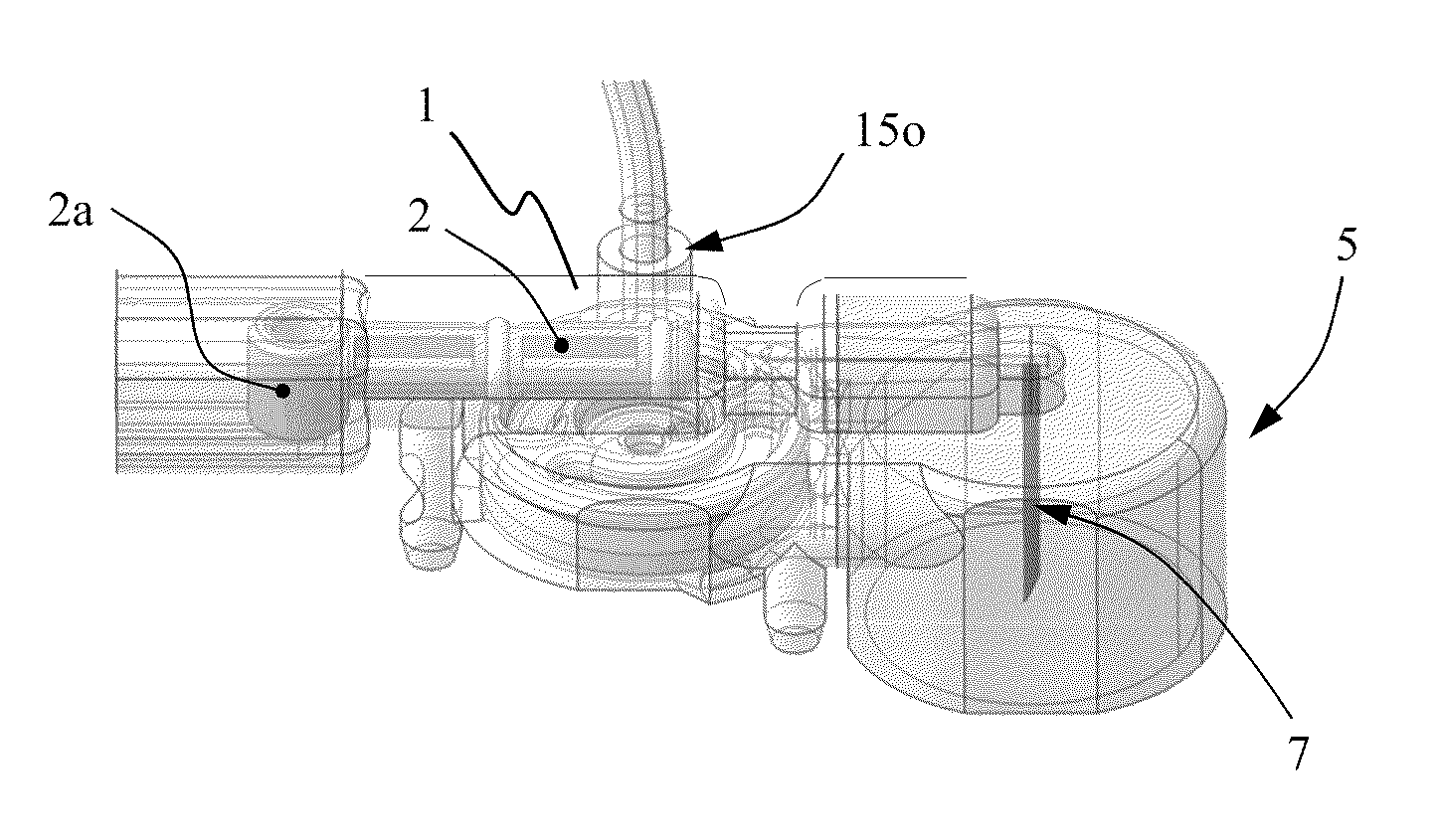
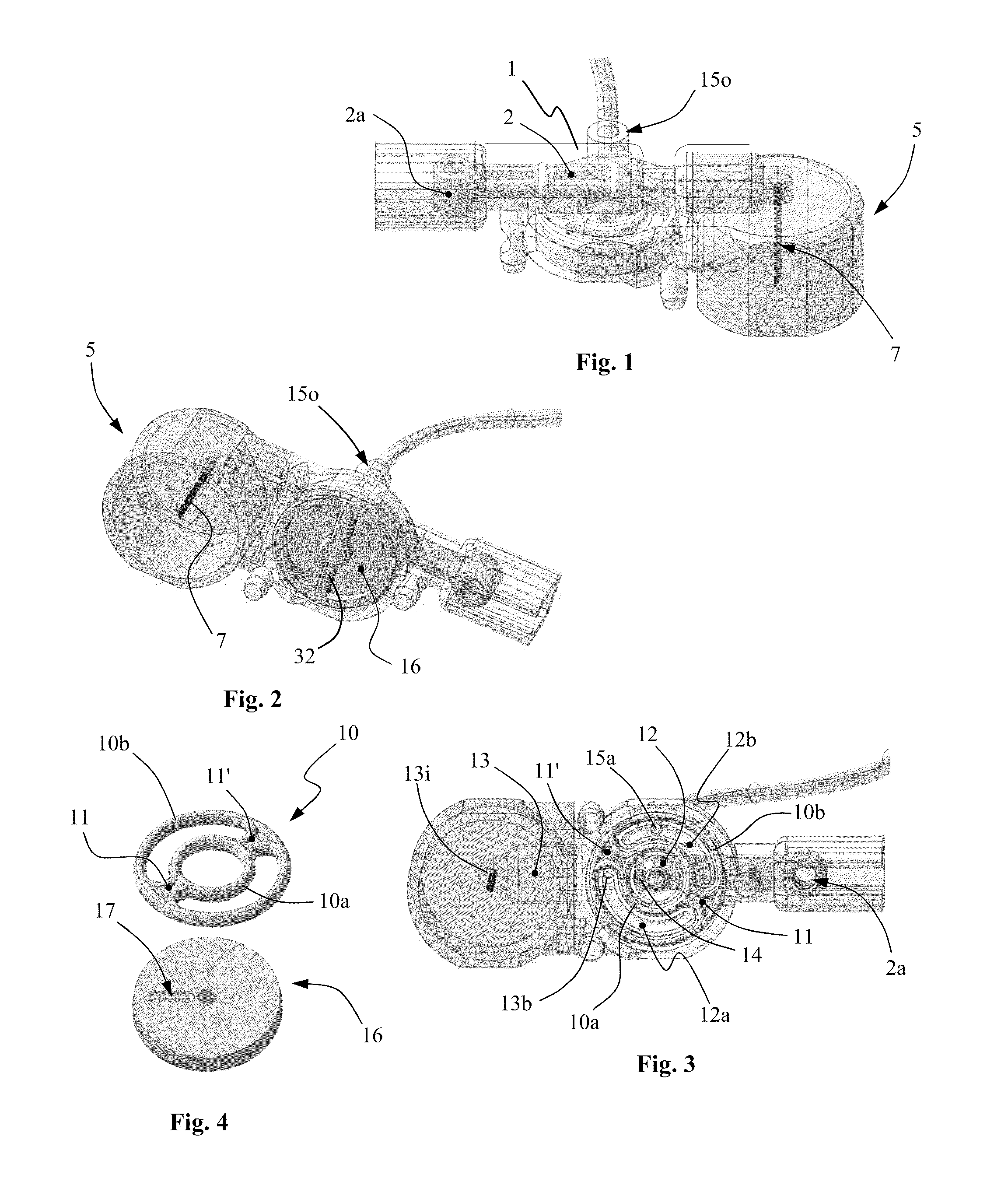
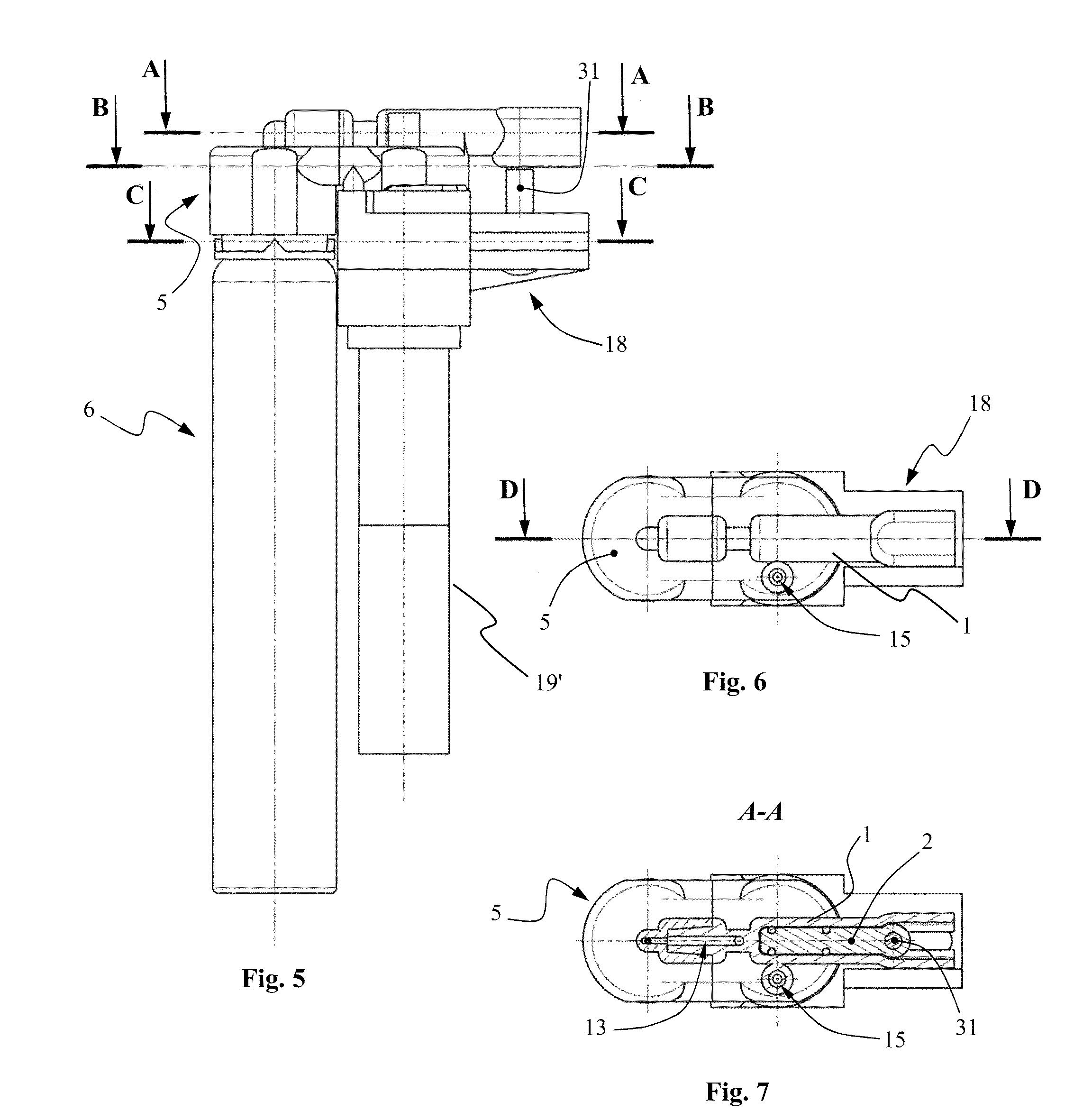
According to the first embodiment of the present invention as shown in FIGS. 1 to 13, the micropump comprises a preferably disposable plastic molded housing 1 having a piston chamber 1′ (FIG. 7) within which a pump piston 2 is mounted so as to be movable back and forth inside chamber 1′, and a cylindrical cap 5 for receiving the head 6′ of a penfill cartridge 6 (FIG. 8). A needle 7 is axially mounted inside the cylindrical cap 5 and is adapted to pierce the cartridge head 6′ when the latter is urged into said cap 5. For this purpose, an inner part 6a of the cartridge head 6′ is made of a soft material to ease the introduction of needle 7 into the cartridge content.

The bottom part of the micropump comprises a cylindrical recess 9 (FIG. 9) adapted to receive a valves system to open and close in turn an inlet and an outlet port 13i, 15o of the pump during a pumping cycle. For this purpose, recess 9 has a bottom surface adapted to receive a gasket 10 (FIG. 4) that compri...

second embodiment

of the Invention

FIGS. 21 to 27 show a micropump and its driving mechanism according to a second embodiment of the invention. This pump is advantageously designed to dispense with the guiding elements of its driving mechanism as described in the first embodiment of the invention particularly in order to minimize the size of the pump and to simplify its manufacturing process.

For this purpose, this pump is made of a lower part 50 and an upper part 51. As shown in FIG. 23, the lower part 50 of the pump contains a hollow cylindrical housing 52 (piston chamber) inside which is arranged a piston 53. Two cylindrical protruding parts 54, 54′ arranged on both lateral sides of the piston 53 are slidably mounted along two half-cylindrical guidance means 55, 55′ located on both lateral sides of the lower part 50 of the pump so that piston 53 can be actuable by a to-and-fro linear movement in a single plane. Lower part 50 of the pump has an upper surface 56 adapted to receive a gasket 57. The gas...

third embodiment

of the Invention

According to a third embodiment of the invention as shown in FIGS. 36 to 43, the micropump is designed for delivering a quasi-continuous flow of a medicinal fluid. This pump comprises a preferably disposable plastic moulded housing 100 having a cylindrical part containing a first and a second chamber 101, 101′ arranged opposite to each other along the longitudinal axis of said cylindrical part (FIGS. 36 and 41). A first and a second piston 102, 102′ are mounted so as to be movable back and forth inside said first and second piston chamber 101, 101′.

The bottom part of the pump housing 100 comprises a cylindrical recess 109 having a flat bottom surface adapted to fixedly receive a gasket 110 (FIG. 37). The gasket 110 comprises three concentric rings, namely an inner, a middle and an outer ring 110a, 110b, 110c, the inner and middle ring 110a, 110b being connected together by a first and a second sealing part 111, 111′ that are diametrically opposed (FIG. 38). The gaske...


PUM

PropertyMeasurementUnit
Angleaaaaaaaaaa

Abstract

A micropump comprises a valve system having one gasket (10) shaped to define three cavities (12, 12a, 12b) connected respectively to a piston chamber, an inlet port and an outlet port of the pump. A valve switching element (16) having at least one groove (17) is movably mounted on the gasket such that, during piston instrokes, said groove moves along a part of the gasket adjacent to the cavities connected respectively to the piston chamber and the inlet port of the pump, thereby creating a leakage between said cavities so that fluid is sucked into the piston chamber during a piston instroke. During piston outstrokes, said groove moves along a part of the gasket adjacent to the cavities connected respectively to the piston chamber and the outlet port of the pump, thereby creating a leakage between said cavities so that fluid is expelled out of the piston chamber through the outlet port during a piston outstroke.

Description

TECHNICAL FIELDThe present invention concerns a micropump and a method for manufacturing thereof. This pump is intended to be used in any industrial, chemical, pharmaceutical or medical application such as enteral, parenteral, IV pumps and is particularly adapted to be used as an insulin pump given that its internal mechanism is designed for obtaining an ultra small and very light pump while being capable to deliver a very small bolus directly from a loadable penfill cartridge.BACKGROUND OF THE INVENTIONInsulin pumps are widely known in the prior art and are an alternative to multiple daily injections of insulin by an insulin syringe or an insulin pen. Insulin pumps make it possible to deliver more precise amounts of insulin than can be injected using a syringe. This supports tighter control over blood sugar and Hemoglobin A1c levels, reducing the chance of long-term complications associated with diabetes. This is predicted to result in a long term cost savings relative to multiple ...

Claims


Application Information

Patent Timeline
IPC IPC(8): A61M5/142A61M1/00F04B17/00B23P15/00
CPCA61M5/14216A61M5/14248Y10T29/49236A61M2005/14268F04B19/006A61M2005/14252
Inventor NAVARRO, THIERRYJUNOD, FLORENT
Owner NAVARRO THIERRY
Why Eureka
Try Eureka