

Analyte Injection System
an electrophoresis and analyte technology, applied in the direction of fluid pressure measurement, liquid/fluent solid measurement, peptide measurement, etc., can solve the problems of reducing the sensitivity of complex samples, etc., to achieve the effect of reducing the amount of sample analy
- Summary
- Abstract
- Description
- Claims
- Application Information
AI Technical Summary
Benefits of technology
Problems solved by technology
Method used
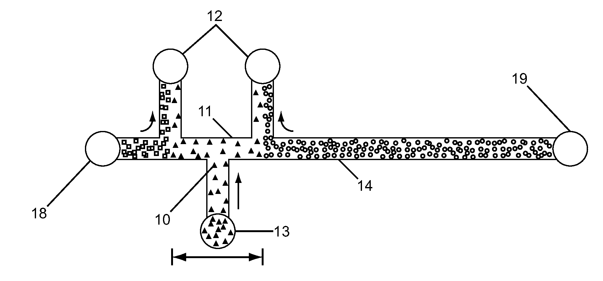
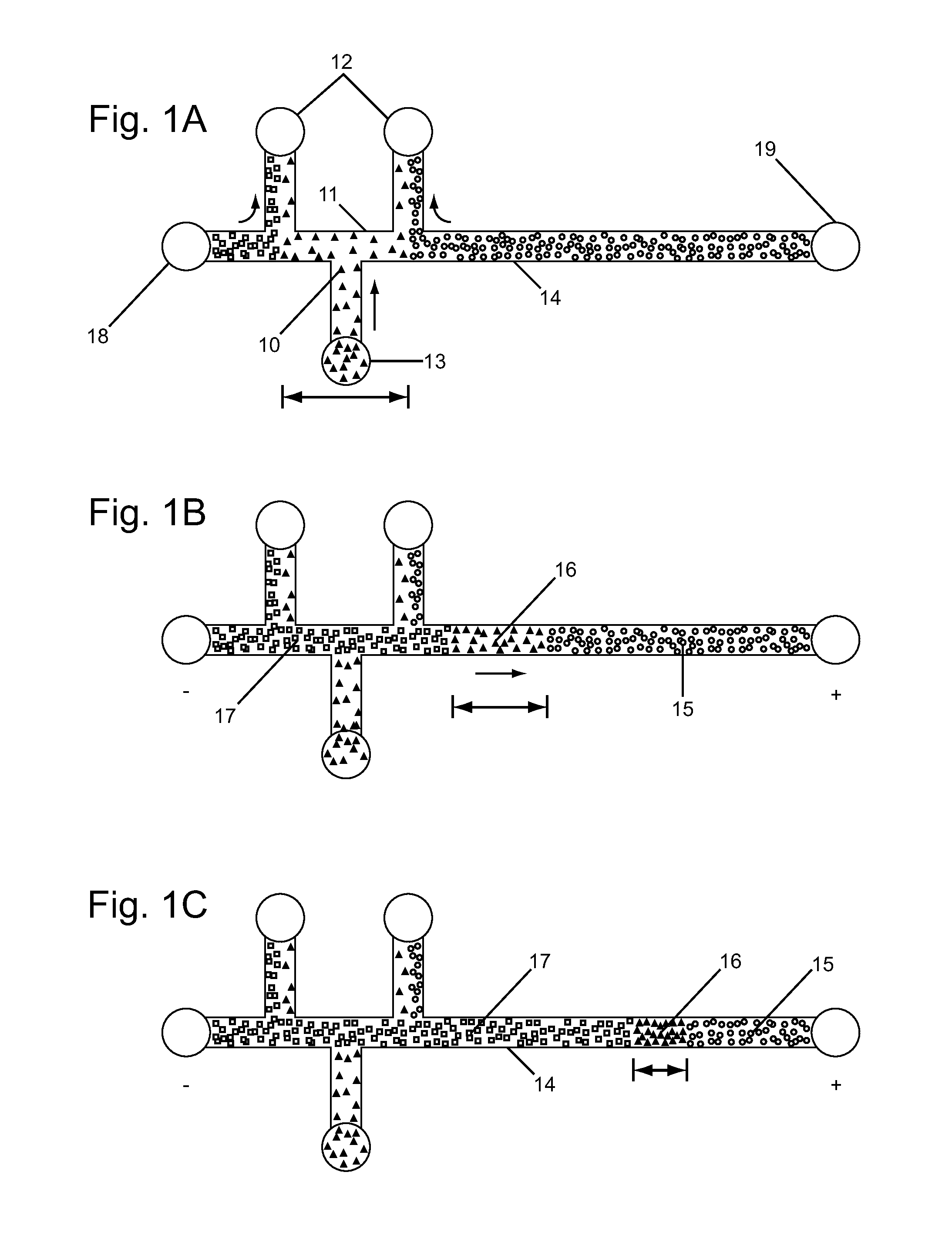
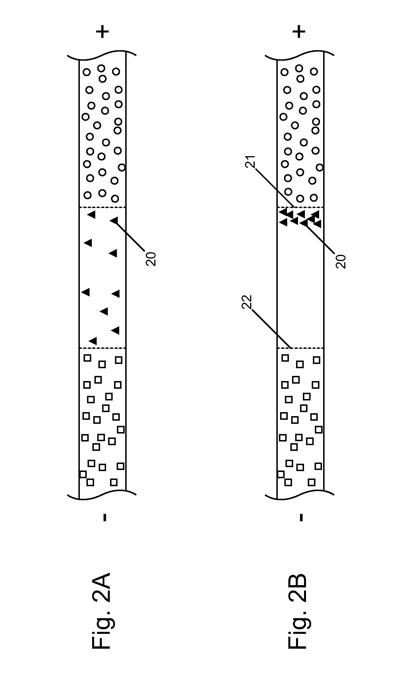
Image

Examples
Embodiment Construction
[0046]Unless otherwise defined herein or below in the remainder of the specification, all technical and scientific terms used herein have meanings commonly understood by those of ordinary skill in the art to which the present invention belongs.
[0047]Before describing the present invention in detail, it is to be understood that this invention is not limited to particular methods or systems, which can, of course, vary. It is also to be understood that the terminology used herein is for the purpose of describing particular embodiments only, and is not intended to be limiting.
[0048]As used in this specification and the appended claims, the singular forms “a”, “an” and “the” include plural referents unless the content clearly dictates otherwise. Thus, for example, reference to “a constituent” can include a combination of two or more constituents; reference to “the analytes” can include one analyte, and the like.
[0049]Although many methods and materials similar, modified, or equivalent to...
PUM
| Property | Measurement | Unit |
|---|---|---|
| width | aaaaa | aaaaa |
| width | aaaaa | aaaaa |
| width | aaaaa | aaaaa |
Abstract
Description
Claims
Application Information