Structural bonding arrangement

a structure and structure technology, applied in the direction of paper/cardboard containers, packaging, transportation and packaging, etc., can solve the problems of affecting the performance of the structure, affecting the stability of the structure, and generating short circuits within the thermoelectric heater, etc., to achieve excellent mechanical properties, increase heating power, and improve the effect of mechanical properties

Active Publication Date: 2011-02-03
GKN AEROSPACE SERVICES LTD
View PDF4 Cites 18 Cited by
  • Summary
  • Abstract
  • Description
  • Claims
  • Application Information

AI Technical Summary

Benefits of technology

[0013]Thus, a heater mat can be provided in between two components of an aircraft leading edge such that the use of attachment means such as rivets need not be used. The position of the heater mat allows heat to flow to, for example, the skin of a leading edge structure that is obscured by a supporting member, while simultaneously providing a means of attaching the supporting member to the skin.
[0014]Moreover, thermop

Problems solved by technology

A problem with known heater mats is that they are difficult to apply to portions of an aircraft leading edge structure (e.g. a skin of the leading edge) that are obscured by other parts of the structure (for example, a supporting rib).
However the flanged portion generally obscures at least a portion of the surface of the skin, inhibiting convenient application of a heater mat to that portion.
Moreover, although a heater mat may be placed in between the skin and the flanged portion, attachment means such as metallic rivets passing through the flange and into the skin would tend to produce short circuits within thermoelectric heater element of the mat.
Although known resins may typically be strong enough to adhere a heater mat to part of an aircraft leading edge, they are typically not strong enough to fix together structural features such as a supporting rib and a

Method used


Image

  • Structural bonding arrangement
  • Structural bonding arrangement
  • Structural bonding arrangement

Examples


Embodiment Construction

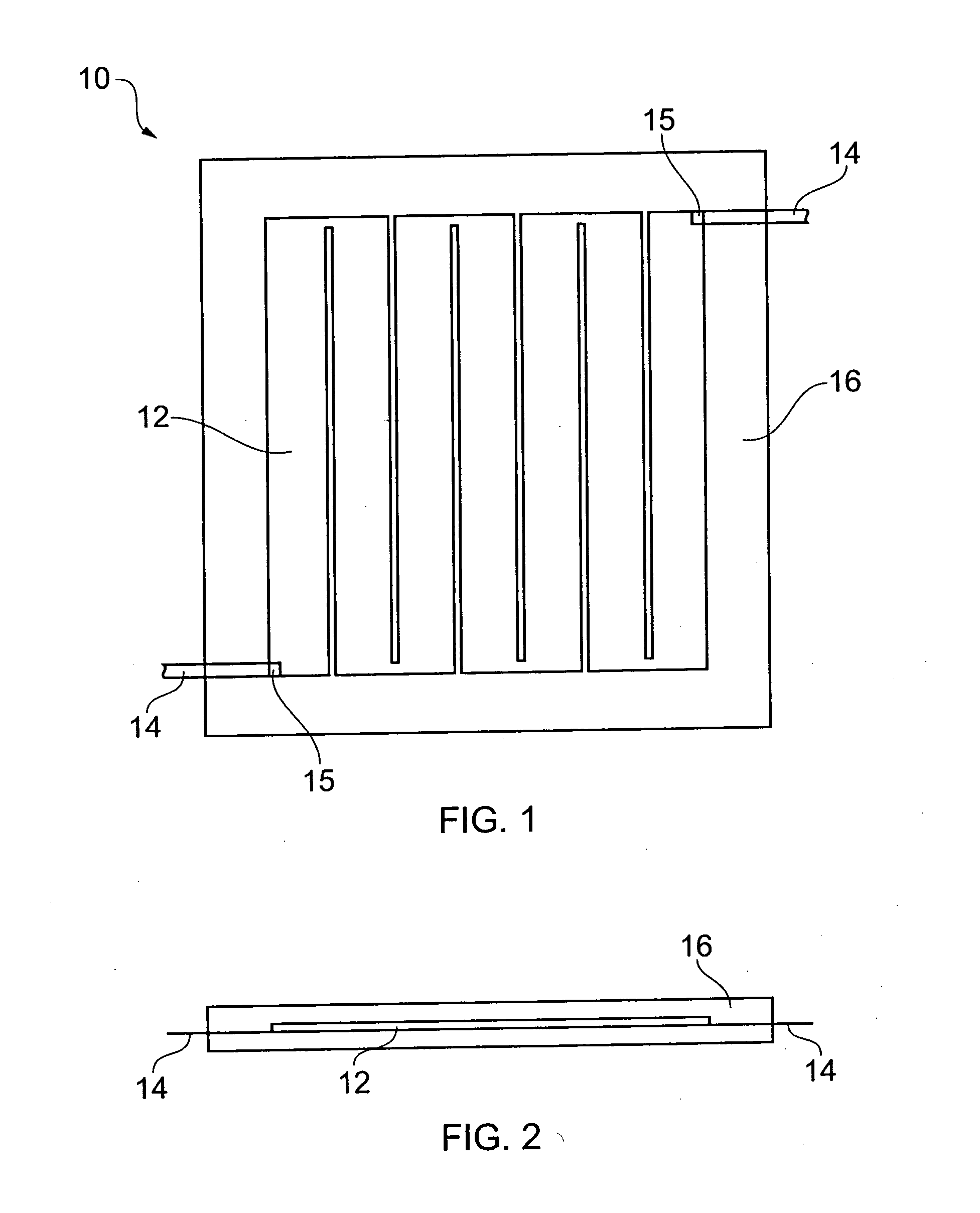
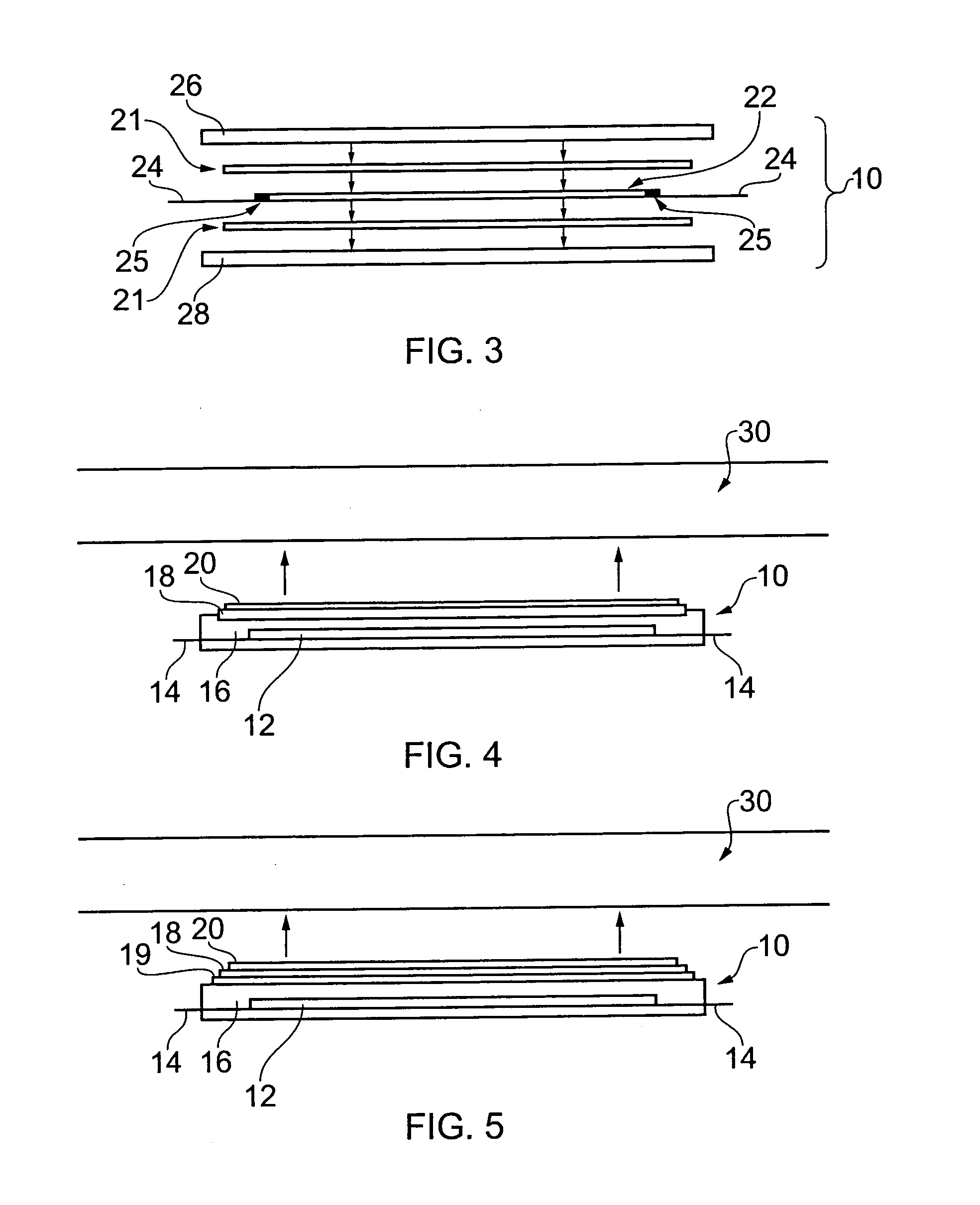
[0033]Particular embodiments will now be described by way of example only in the following with reference to the accompanying drawings.

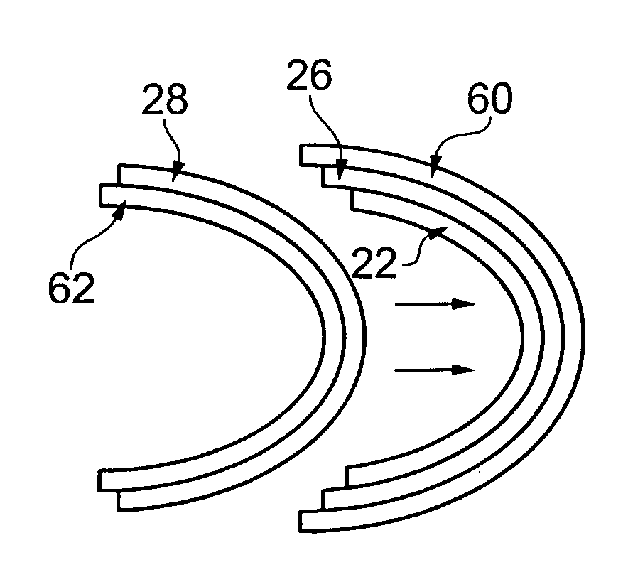
[0034]According to an embodiment of this invention, there can be provided a leading edge component for an aircraft. The component includes a supporting rib, a skin, and a thermoelectric heater mat that is located between the rib and the skin. The skin and the rib are bonded together using a thermoplastic layer which is included in the heater mat. The thermoplastic layer also provides protection for the heater element of the heater mat. Embodiments of this invention also provide methods of making such a leading edge component.

[0035]Thermoplastics are characterised by their material properties as a function of temperature. In particular, thermoplastic materials are plastic (deformable) in a temperature between an upper transition temperature Tm and a lower transition temperature Tg. Above Tm, thermoplastic materials melt to form a liquid. Below Tg they...


PUM

PropertyMeasurementUnit
Metallic bondaaaaaaaaaa
Heataaaaaaaaaa
Electrical resistivityaaaaaaaaaa

Abstract

A leading edge component (30) for an aircraft. The component includes at least one supporting rib (40); a skin of the leading edge; and an ice-protection system comprising a thermoelectric heater mat (10) located between the rib and the skin, the heater mat comprising an electrically resistive heater element (12, 22) embedded in a thermoplastic layer (16, 26, 28), wherein the rib is bonded to the skin by the thermoplastic of the heater mat. A method making a leading edge component for an aircraft. The method includes: providing at least one rib, a skin of the leading edge, and an ice-protection system comprising a thermoelectric heater mat having an electrically resistive heater element embedded in a thermoplastic layer; locating the heater mat between the rib and the skin; and bonding the rib to the skin using the thermoplastic of the heater mat.

Description

BACKGROUND OF THE INVENTION[0001]This invention relates to structural bonding arrangements in aircraft leading edge components that include an ice-protection system.[0002]Known heater mats such as those that are used as part of a de-icing system for a leading edge of an aircraft include a thermoelectric heater element and one or more layers of a dielectric material such as Kapton. The dielectric protects the thermoelectric heater element and can serve to electrically insulate it from a metallic surface (such as an inner surface of a skin of an aircraft leading edge) to which the heater mat is to be applied.[0003]A problem with known heater mats is that they are difficult to apply to portions of an aircraft leading edge structure (e.g. a skin of the leading edge) that are obscured by other parts of the structure (for example, a supporting rib). Known supporting ribs typically include a flanged portion through which attachments such as rivets may pass to fix the rib to the skin of the...

Claims


Application Information

Patent Timeline
IPC IPC(8): B64D15/12B29C65/00
CPCH05B2203/017H05B3/36Y10T156/10B64D15/12H05B2203/013H05B2203/003B64F5/30
Inventor BARDWELL, ANTHONY EDWARD
Owner GKN AEROSPACE SERVICES LTD
Why Eureka
Try Eureka