
High efficiency and long life optical spectrum conversion device and process

Inactive Publication Date: 2011-02-03
JONES GARY WAYNE
View PDF13 Cites 87 Cited by
  • Summary
  • Abstract
  • Description
  • Claims
  • Application Information

AI Technical Summary

Benefits of technology

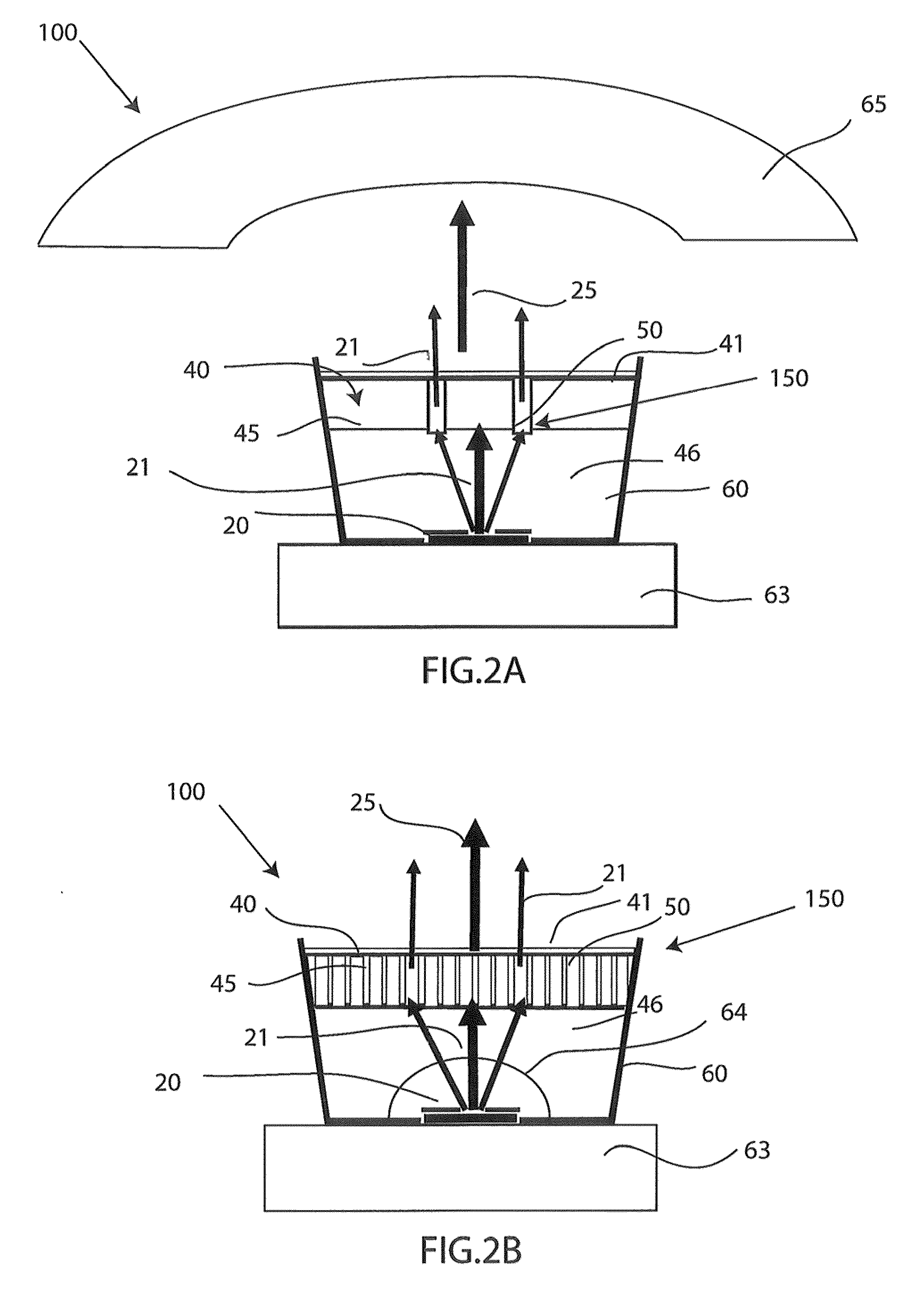
[0009]A third aspect relates generally to a method of improving life and efficiency of spectral conversion comprising providing a plurality of discrete units, the plurality of discrete units including transparent discrete units and dyed discrete units, dying the dyed discrete units with a photoluminescent material at a concentration greater than or equal to an amount sufficient to absorb and convert substantially all input light from a light source to a desired output spectrum, providing a coating material around the plurality of discrete units, wherein the coating material binds the plurality of discrete units to form a matrix, further wherein a thickness of the coating material determines the distance between each of the plurality of discrete units, and positioning the plurality of discrete units proximate the light source, wherein the input light passing through the transparent discrete units is not converted, and the input light passing through the doped discrete units is converted to red and green wavelengths, further wherein the emitted input light and the converted red and green light correspond to the desired output spectrum to produce one or more colors.

Problems solved by technology

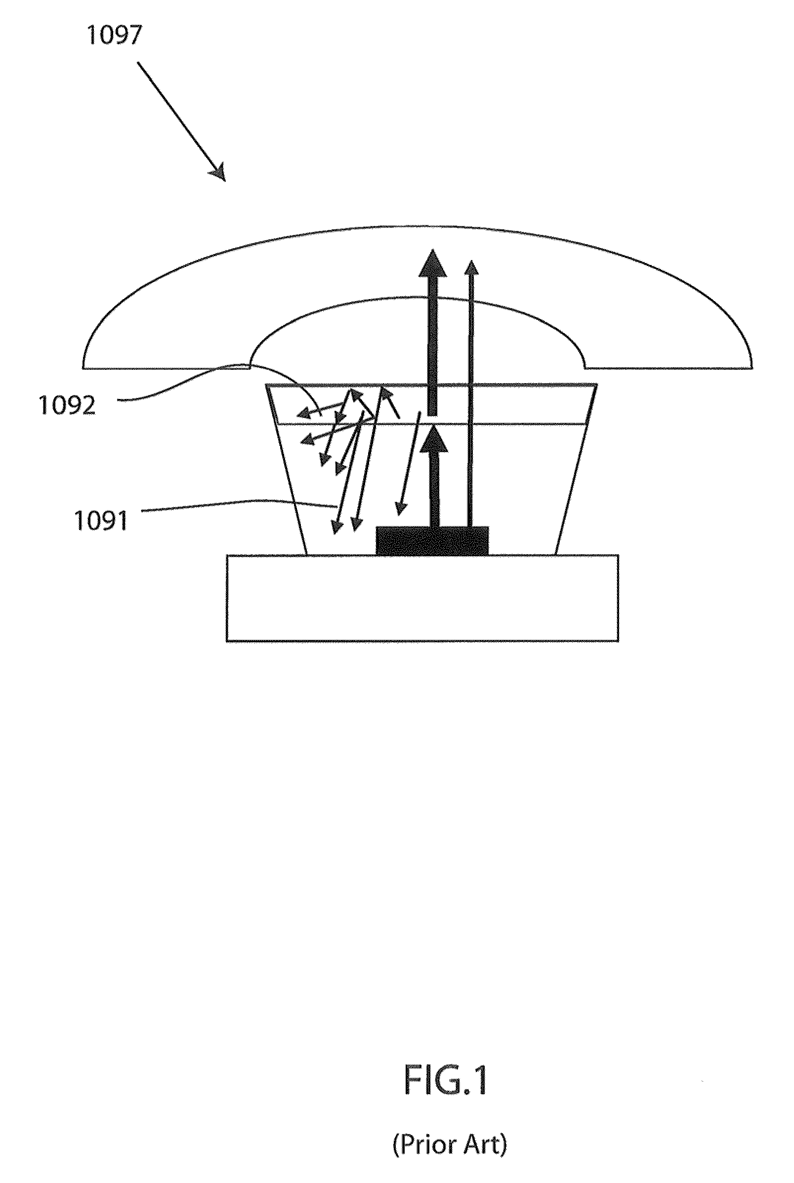
Prior white-light and multicolor light emitting diode (LED) lighting color conversion processes involving inorganic phosphor powders waste a substantial portion of the photons from the LED due to light scattering, light trapping, and quantum yield conversion losses in most photoluminescent phosphor matrix structures.
Light scattering and light trapping within a color converter and LED combination is a problem associated with white LED lighting because it can lead to an overall waste of photons, as well as reduction in energy efficiency in a white light emitting LED lamp.
Furthermore, light directionality of color converted lights has been limited by the omni-directional light emission characteristics of these color converters.

Method used


Image

  • High efficiency and long life optical spectrum conversion device and process
  • High efficiency and long life optical spectrum conversion device and process
  • High efficiency and long life optical spectrum conversion device and process

Examples


Embodiment Construction

[0047]Although certain embodiments will be shown and described in detail, it should be understood that various changes and modifications may be made without departing from the scope of the appended claims. The scope will in no way be limited to the number of constituting components, the materials thereof, the shapes thereof, the relative arrangement thereof, etc., and are disclosed simply as an example of an embodiment. The features and advantages are illustrated in detail in the accompanying drawings, wherein like reference numerals refer to like elements throughout the drawings.

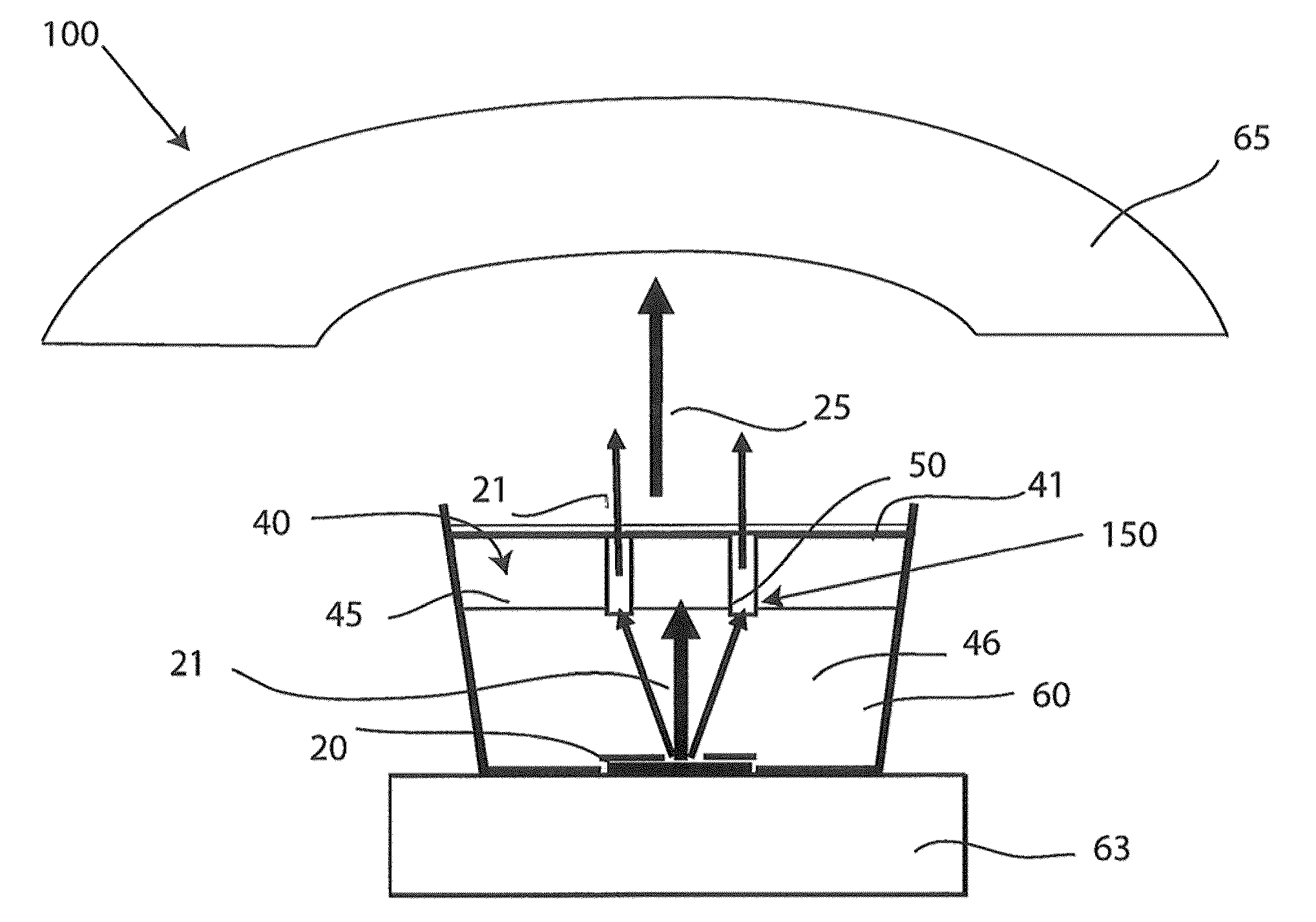
[0048]Referring to drawings, FIG. 1 depicts a conventional white light emitting diode (LED) lamp 1097 exhibiting problems such as light trapping 1091 and light scattering 1092. The conventional white LED lamp 1097 typically involves the use of inorganic phosphor powders in transparent matrices, which result in substantial light trapping 1091, light scattering 1092, and a significant loss of light output. Lo...


PUM


Abstract

A spectral conversion device including a plurality of discrete units dyed with a photoluminescent material at a concentration greater than or equal to an amount sufficient to absorb and convert substantially all input light from a light source to a desired output spectrum, and a coating material disposed around the discrete units, wherein the coating material binds the plurality of discrete units to form a matrix, wherein when the plurality of discrete units are positioned over the light source, the input light passing through the transparent discrete units is not converted, and the input light passing through the doped discrete units is converted to red and green wavelengths, further wherein the emitted input light and the converted red and green light correspond to the desired output spectrum to produce one or more colors. An associated method and an associated device used with flat panel image displays are also provided.

Description

RELATED APPLICATIONS[0001]This non-provisional application claims priority to a U.S. Provisional Application Ser. No. 61 / 181,447 filed May 27, 2009 with the United States Patent and Trademark Office.FIELD OF TECHNOLOGY[0002]The following relates generally to an apparatus and method for increasing the useful life and energy efficiency of spectral conversion, more specifically to embodiments of a photoluminescent color converter matrix.BACKGROUND OF TECHNOLOGY[0003]Prior white-light and multicolor light emitting diode (LED) lighting color conversion processes involving inorganic phosphor powders waste a substantial portion of the photons from the LED due to light scattering, light trapping, and quantum yield conversion losses in most photoluminescent phosphor matrix structures. The high index of refraction and birefringence of many inorganic phosphor grains cause light scattering, preventing the majority of visible light from being emitted in the forward direction. Light scattering an...

Claims


Application Information

Patent Timeline
IPC IPC(8): G02F1/13357F21V9/16F21V8/00G02B27/56H01S3/091
CPCH01L33/50H01L2933/0041H01L33/60
Inventor JONES, GARY WAYNE
Owner JONES GARY WAYNE
Learn More