
Compact auto focus lens module with piezoelectric actuator

a piezoelectric actuator and auto-focus technology, applied in the direction of instruments, printers, cameras, etc., can solve the problems of difficult application to compact auto-focus lens modules, and not suitable for mini-sized lens modules

Inactive Publication Date: 2011-02-03
SILITECH TECH CORP
View PDF21 Cites 12 Cited by
  • Summary
  • Abstract
  • Description
  • Claims
  • Application Information

AI Technical Summary

Benefits of technology

[0008]It is another object of the present invention to provide a compact auto focus lens module with a piezoelectric actuator with broader applications in which the elastic member is a coil spring so as to make the lens module have more applications. For further minimization of the volume, the elastic member can be an elastic pad made from elastic foam material or rubber. The elastic member can also be a leaf spring.

Problems solved by technology

However, the plate spring has complicated structure, high volume requirement and large space, it is not suitable for mini-sized lens modules.
However, conventional ultrasonic motors for movement of the lens barrel have shortcomings of complicated structure, high cost or large volume in designs of the guiding rod or friction generation so that they are difficult to be applied to compact auto focus lens modules.

Method used


Image

  • Compact auto focus lens module with piezoelectric actuator
  • Compact auto focus lens module with piezoelectric actuator
  • Compact auto focus lens module with piezoelectric actuator

Examples


embodiment 1

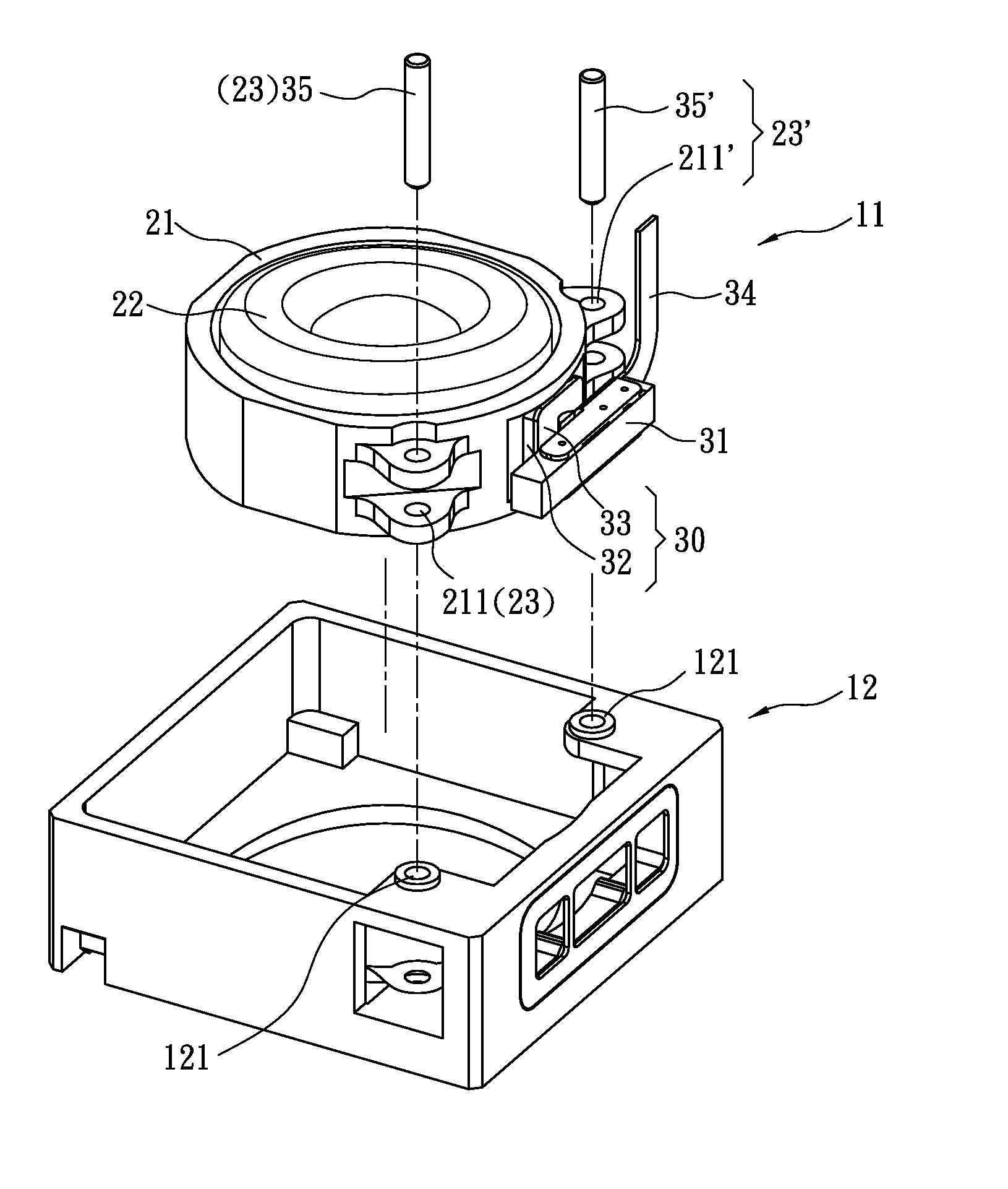
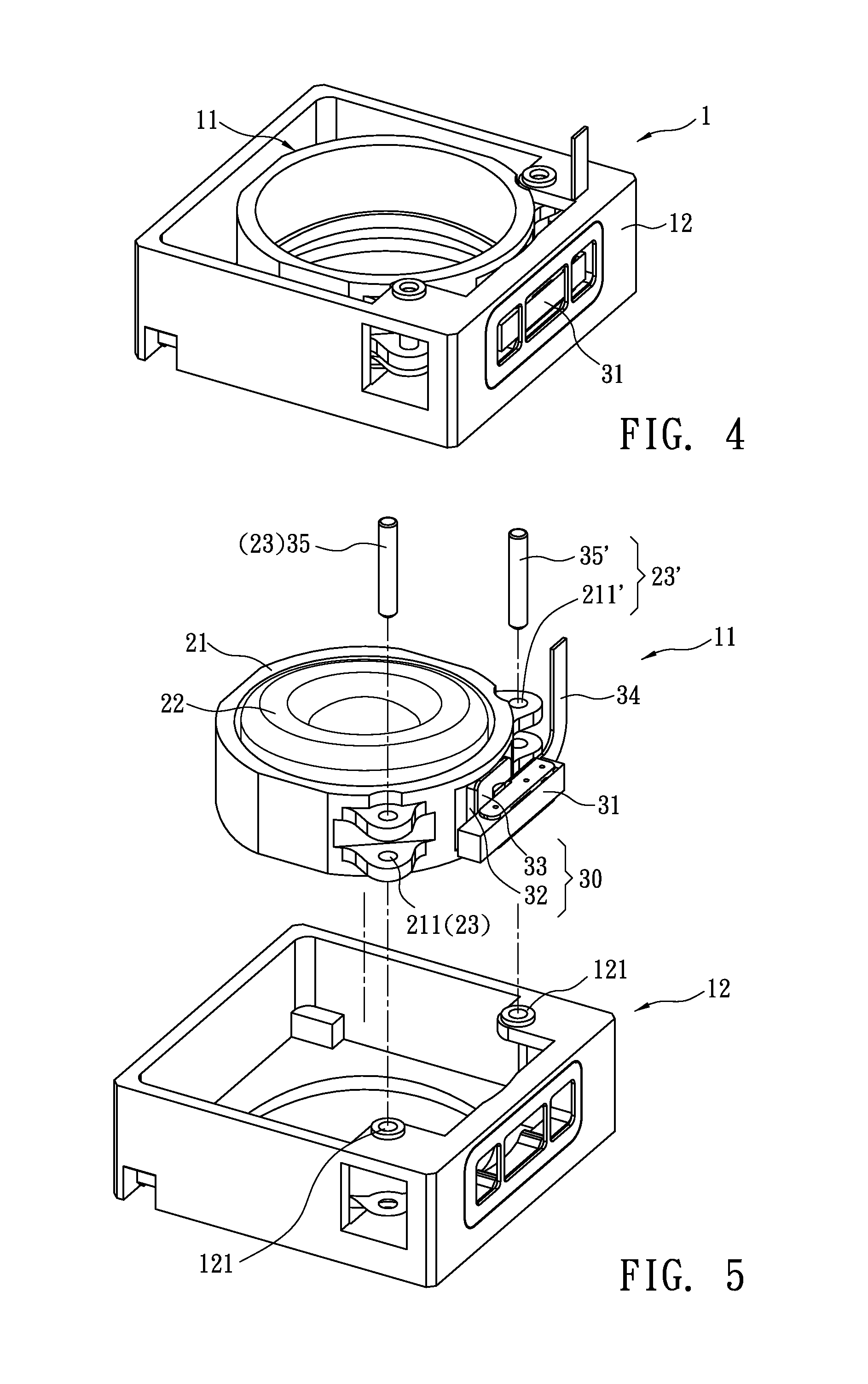
[0017]Refer from FIG. 4 to FIG. 6, a compact auto focus lens module with a piezoelectric actuator 1 according to the present invention includes a piezoelectric actuator 31, a lens module 11 and a frame 12. The piezoelectric actuator 31, and the lens module 11 are mounted in the frame 12. The piezoelectric actuator 31 whose electrode 34 is connected with a voltage controller (not shown in figure) is fixed in the frame 12. Generally, due to converse piezoelectric effect of piezoelectric materials, the application of an electrical field creates mechanical deformation in the materials and further leads to displacement. According to motions of piezoelectric materials, the piezoelectric actuator is classified into: (1) linear vertical motion: having single-layer type and multi-layer type, with advantages of high rigidity and large axial thrust force. (2) curved horizontal motion: including Unimorph type and Bimorph type. The piezoelectric actuator that moves in this way has larger displac...

embodiment 2

[0021]Refer to FIG. 4 and FIG. 7, this embodiment has similar structure with the above embodiment but the elastic member 32 of the elastic element 30 is a coil spring 322. One end of the coil spring 322 is fixed on one side of the lens barrel 21 while the other end thereof is glued on a metal member 33. By the spring tension of the coil spring 322, the metal member 33 presses against the piezoelectric actuator 31 so as to generate a friction on an interface between the metal member 33 and the piezoelectric actuator 31.

embodiment 3

[0022]Refer to FIG. 4 and FIG. 8, this embodiment has similar structure with the above embodiment but the elastic member 32 of the elastic element 30 is a leaf spring 323. One end of the leaf spring 323 is fixed on one side of the lens barrel 21 while the other end thereof is glued on a metal member 33. By the recovery force of the leaf spring 323, the metal member 33 presses against the piezoelectric actuator 31 so as to generate a friction on an interface between the metal member 33 and the piezoelectric actuator 31.


PUM


Abstract

A compact auto focus lens module with a piezoelectric actuator revealed includes a piezoelectric actuator, an elastic element, at least two guiding fixtures, and a lens barrel with an optical lens set therein. By elastic force of the elastic element, a friction is generated between the lens barrel and the piezoelectric actuator. While being applied with a voltage, the lens barrel driven by the movement of the piezoelectric actuator moves along the optical axis under the guidance of the guiding fixtures. Due to fewer elements, compact volume, and light weight, the design is applied to miniature auto focus lens modules so as to achieve effects of fast movement, stable focusing and reduced tilting.

Description

BACKGROUND OF THE INVENTION[0001]The present invention relates to a compact auto focus lens module with a piezoelectric actuator, especially to an auto focus lens module in which movement of an optical lens set is controlled by displacement and friction produced by deformation of the piezoelectric actuator for focusing.[0002]Digital cameras or mobile phone cameras include a lens module that drives optical lens set moving along an optical axis so as to achieve autofocusing and / or zoom in / zoom out. One of the movement ways of the optical lens set is by Voice coil motor (VCM). After a current being applied to a coil, a driving force is generated in an electromagnetic field created by a permanent magnet so as to drive the optical lens set moving along the optical axis. Such design can reduce volume of lens modules so that it has been applied to mini-sized cameras, camera-equipped cellular phone or web-cameras broadly, as shown in US2008 / 0013196, U.S. Pat. No. 6,594,450, U.S. Pat. No. 7,...

Claims


Application Information

Patent Timeline
Patent Type & Authority Applications(United States)
IPC IPC(8): G02B7/09
CPCG02B7/08
Inventor SHYU, SAN-WOEICHOU, CHIN-YIYU, TENG-CHIEN
Owner SILITECH TECH CORP
Learn More