Elongated body for deployment in a coronary sinus

a deployment body and coronary sinus technology, applied in the field of surgery and cardiology, can solve the problems of congestive heart failure, shortness of breath, fainting,

Active Publication Date: 2011-02-03
MOR RES APPL LTD
View PDF15 Cites 175 Cited by
  • Summary
  • Abstract
  • Description
  • Claims
  • Application Information

AI Technical Summary

Benefits of technology

[0111]In some embodiments, when deployed a first anchor substantially maintains a shape to support the surface of a heart which is being contacted and distributing p

Problems solved by technology

Mitral valve insufficiency leads to many complications including arrhythmia, atrial fibrillation, cardiac palpitations, chest pain, congestive heart failure, fainting, fatigue, low cardiac output, orthopnea, paroxysmal nocturnal dyspnea, pulmonary edema, shortness of breath, and sudden death.
Initially, ischemic mit

Method used


Image

  • Elongated body for deployment in a coronary sinus
  • Elongated body for deployment in a coronary sinus
  • Elongated body for deployment in a coronary sinus

Examples


first embodiment

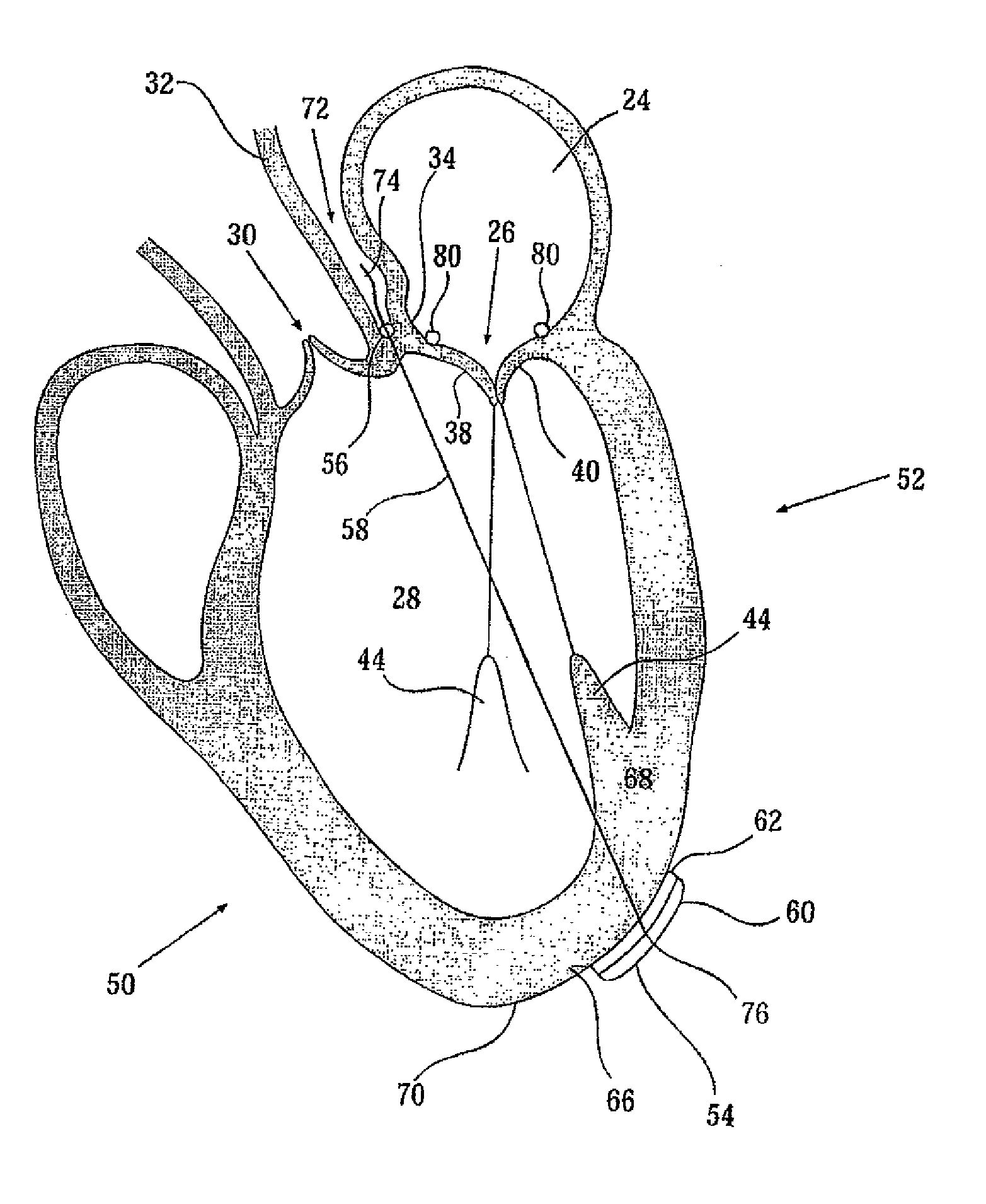
[0312]In FIGS. 4A to 4E, a device for applying pressure, force and / or movement limitation to a portion of a mammalian heart of the present invention, device 52 is depicted. In FIG. 4A, device 52 is depicted deployed in an ischemic heart 50. Device 52 comprises three discrete components: a pad assembly as a first anchor 54, a felt rod as a second anchor 56 and a suture strand as a tensioning member 58.

[0313]First anchor 54 is depicted in detail in FIG. 4B in front view and side view. First anchor 54 is a single assembly consisting essentially of two components: a slightly-elastic curved plate of stainless steel mesh 60, 3 cm by 5 cm wide (having a surface area of about 12 cm2) and a pliant layer 62 of 0.5 mm thick surgical felt located on the concave face of plate 60 so as to define a concave contact face 64. First anchor 54 is configured to be deployed entirely outside heart 50 so that contact face 64 contacts a surface 66 of an external wall 68 of left ventricle 28 of heart 50 in p...

second embodiment

[0329]In FIGS. 5A and 5B, a device of the present invention, device 82 is depicted, in FIG. 5A deployed in an ischemic heart 50. In device 82, the distance between first anchor 54 and second anchor 56 is adjustable when deployed in a heart 50, and even when heart 50 is beating.

[0330]First anchor 54 of device 82 is substantially similar to first anchor 54 of device 52 but is made of PMMA (polymethyl methylacrylate) instead of stainless steel. First anchor 54 of device 82 is configured so that tensioning member 58 is reversibly securable to first anchor 54 when device 82 is deployed in a heart 50 and, in some embodiments, while heart 50 is beating. Specifically, first anchor 54 is provided with a retaining nut 84 with an axial hole passing therethrough to accommodate a tensioning member 58 and a locking screw 86 disposed in a screw hole perpendicular to the axial hole. Such a construction allows the location along tensioning member 58 where tensioning member 58 is secured to first anc...

third embodiment

[0341]In FIGS. 6A and 6B, a device of the present invention, device 92 is depicted, in FIG. 6A deployed in an ischemic heart 50. In device 92, first anchor 54 comprises two discrete assemblies 54a and 54b with two discrete tensioning members 58a and 58b. Each tensioning member 58a and 58b defines a distance between a second anchor 56 and a respective assembly 54a and 54b. Each of the distances is independently adjustable when device 92 is deployed in a heart 50 even when heart 50 is beating.

[0342]Each first anchor assembly 54a and 54b of device 82 is substantially similar to pads used in a Coapsys® device (Myocor, Inc., Maple Grove, Minn., USA).

[0343]Second anchor 56 of device 92 is a 2 cm length of surgical felt having a 3 mm diameter oblate semicircular cross section. Second anchor 56 of device 92 is configured allowing a tensioning member 58a or 58b to be reversibly securable to second anchor 56 when device 92 is deployed in heart 50 and, in some embodiments, while heart 50 is be...


PUM


Abstract

Coronary sinus ring apparatus, including an elongated body for deployment in a coronary sinus, an aperture in a long side of the body, at least a partial lumen extending from one end of the elongated body to at least the aperture, and a guide within the elongated body positioned and shaped to guide an element inserted along the lumen to the aperture. Apparatus for treating a heart, including a delivery tube sized for and adapted for insertion into a body, a sharp tip adapted to be pushed through cardiac muscle, an elongate tensioning element, and a foldable anchor adapted to couple the elongate tension element to cardiac muscle tissue, wherein the delivery tube encloses one or both of the elongate tensioning element and the foldable anchor. Related apparatus is also described.

Description

RELATED APPLICATIONS[0001]This application is a Continuation-In-Part of and claims priority from U.S. Provisional Application No. 61 / 219,854, filed on Jun. 24, 2009; and from PCT Patent Application Number PCT / IL2008 / 001645 entitled “Methods and devices for treatment of a heart” filed on Dec. 21, 2008.FIELD OF THE INVENTION[0002]The present invention, in some embodiments thereof, relates to the field of surgery and Cardiology and in some embodiments to methods, devices and kits potentially useful, for example, for applying force to at least a portion of a mammalian heart, for example to change the shape of the left ventricular cavity, to support a sagging cardiac wall (e.g., caused by remodeling); to improve mitral valve leaflet coaptation and / or to prevent and / or ameliorate mitral valve insufficiency and / or heart failure, to assist contractility of sagging cardiac wall. Some embodiments of the present invention allow, for example, improving mitral leaflet coaptation, for example in ...

Claims


Application Information

Patent Timeline
IPC IPC(8): A61F2/24
CPCA61B17/00234A61B17/04A61B17/0487A61B2017/00986A61B2017/0417A61F2/2487A61B2017/0488A61B2017/0496A61B2017/06052A61F2/2451A61F2/2466A61B2017/0448
Inventor ZLOTNICK, AMNONISRAEL, HENRY M.HARARI, BOAZ
Owner MOR RES APPL LTD
Why Eureka
Try Eureka