
Exhaust gas purifying apparatus

a technology of exhaust gas purification and purification apparatus, which is applied in mechanical apparatus, exhaust treatment electric control, machines/engines, etc., can solve the problems of deteriorating efficiency of nox reduction in comparison to urea water usage, difficulty in providing distance of apparatus, and increase in quantity of unreacted urea water supplied to scr catalytic module without hydrolysis into ammonia

Inactive Publication Date: 2011-02-10
TOYOTA IND CORP
View PDF4 Cites 16 Cited by
  • Summary
  • Abstract
  • Description
  • Claims
  • Application Information

AI Technical Summary

Benefits of technology

An exhaust gas purification apparatus includes an oxidation catalyst provided in a passage through which exhaust gas flows, a urea decomposition accelerator, a selective catalytic reduction catalyst provided downstream of the urea decomposition accelerator and a...

Problems solved by technology

The exhaust gas purification apparatus including the urea SCR system and the DPF has many components provided between the engine and the muffler and requires a large space for mounting of such components to a vehicle.
However, when the structural space of the exhaust gas purification apparatus is reduced, it is difficult for the apparatus to provide a distance between the hydrolytic catalytic module and the SCR catalytic module that is long enough to ensure the reaction time for urea water to be hydrolyzed.
Therefore, if the structural space of the exhaust gas purification apparatus attempted to be reduced, the quantity of unreacted urea water supplied to the SCR catalytic module without being hydrolyzed into ammonia increases, with the result that the efficiency of the reduction of NOx in comparison to urea water usage deteriorates.

Method used


Image

  • Exhaust gas purifying apparatus
  • Exhaust gas purifying apparatus
  • Exhaust gas purifying apparatus

Examples


first embodiment

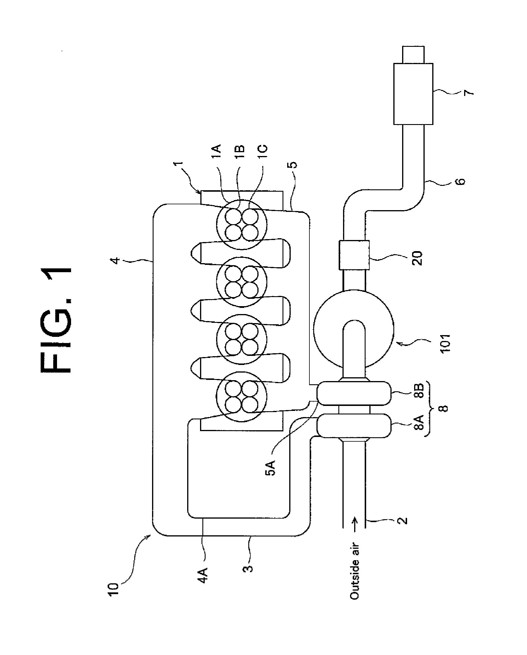
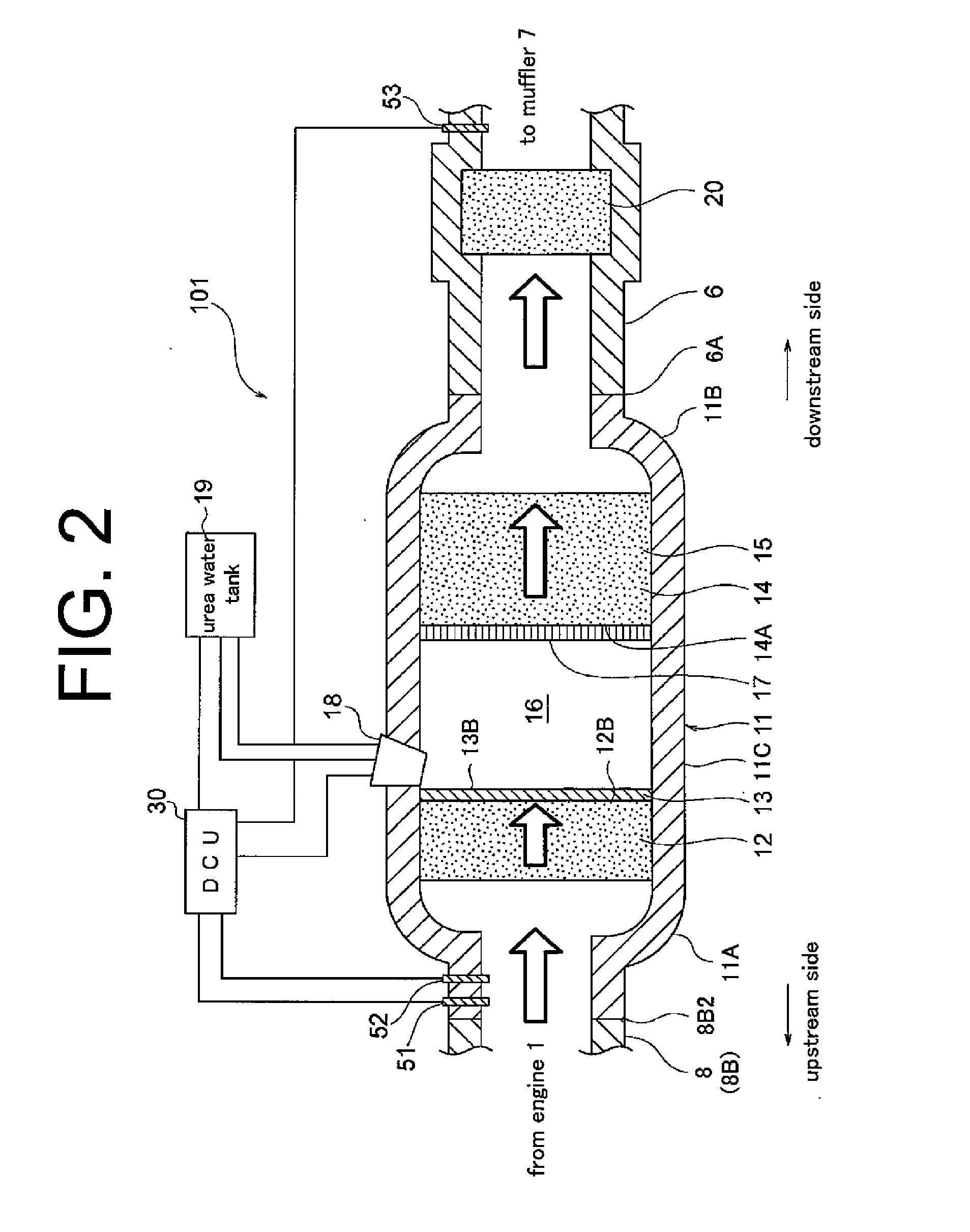
The following will describe the embodiments of the exhaust gas purification apparatus according to the present invention with reference to FIGS. 1 through 3. Referring to FIGS. 1 and 2 showing the first embodiment, the exhaust gas purification apparatus which is designated generally by 101 and its associated components will be described. The exhaust gas purification apparatus 101 is employed in a vehicle equipped with a diesel engine.

Referring to FIG. 1, an engine assembly including an engine 1 and the exhaust gas purification apparatus 101 is designated generally by reference numeral 10. The engine 1 has a plurality of cylinders 1A each having an intake port 1B to which an intake manifold 4 is connected for distributing intake air to the respective cylinders 1A. The intake manifold 4 has an inlet 4A to which an engine intake pipe 3 is connected and the engine intake pipe 3 is further connected to a compressor housing 8A of a turbocharger 8. The compressor housing 8A is connected to...

second embodiment

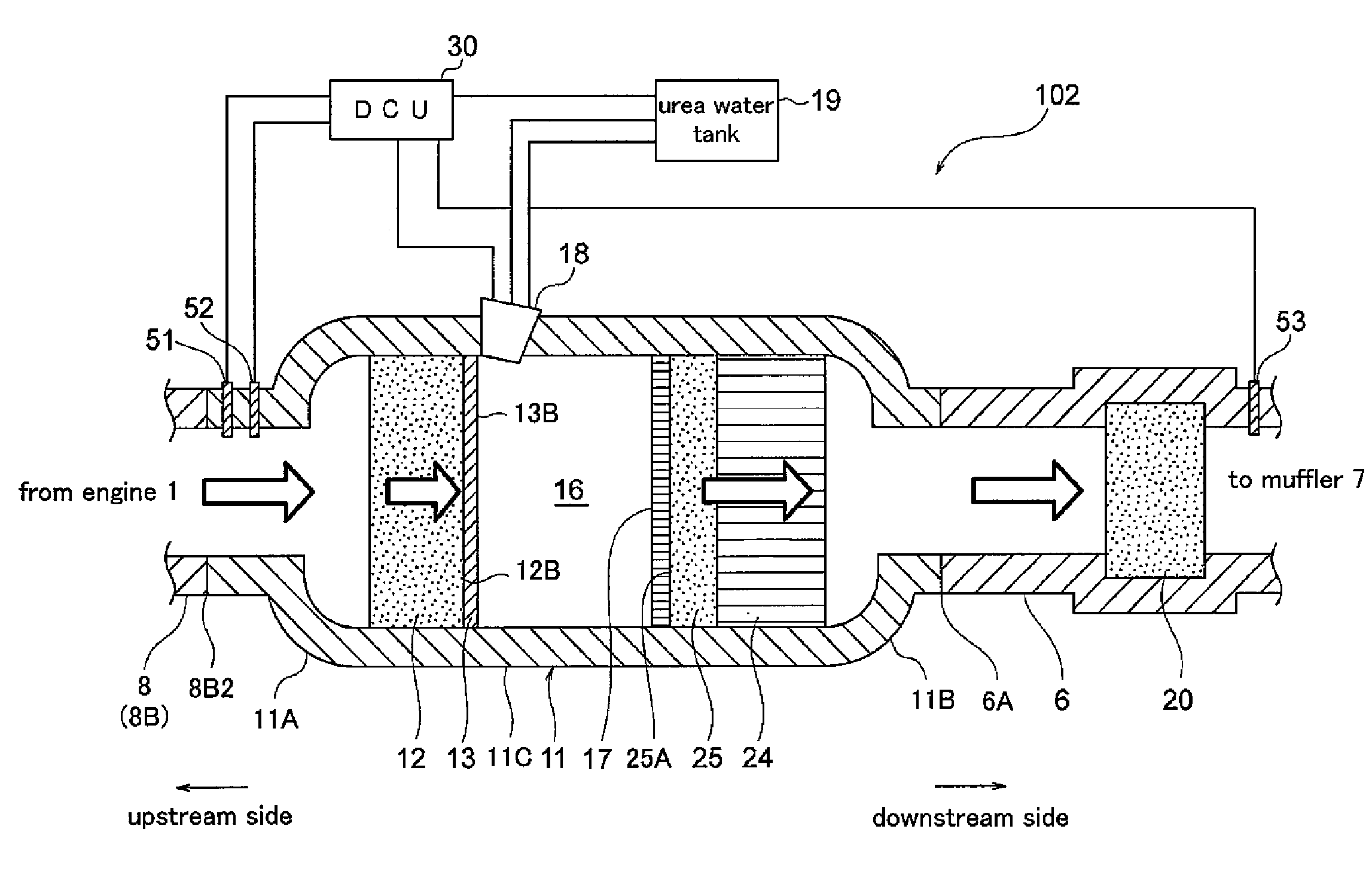
In the second embodiment, the oxidation catalyst layer 12, the SCR catalyst layer 25, the DPF 24 and the injection valve 18 are all provided in the casing 11 of the exhaust gas purification apparatus 102, but the present invention is not limited to this structure. For example, only the DPF 24 may be provided outside the casing 11 separately from the other components.

In the first and second embodiments, the oxidation catalyst layer 20 is provided separately from the exhaust gas purification apparatuses 101, 102, but the present invention is not limited to this structure. The oxidation catalyst layer 20 may be provided inside the casing 11 downstream of the DPF 14, 24 of the exhaust gas purification apparatuses 101, 102, respectively.

The injection valve 18 is provided downstream of the oxidation catalyst layer 12 so as to supply urea water to the hydrophilic layer 13 in the exhaust gas purification apparatuses 101, 102 according to the first and the second embodiments, respectively, b...


PUM


Abstract

An exhaust gas purification apparatus includes an oxidation catalyst provided in a passage through which exhaust gas flows, a urea decomposition accelerator, a selective catalytic reduction catalyst provided downstream of the urea decomposition accelerator and a urea water supplying device for supplying urea water to the urea decomposition accelerator. The urea decomposition accelerator is provided downstream end surface of the oxidation catalyst and has at least one of hydrophilic function and hydrolytic catalytic function.

Description

BACKGROUND OF THE INVENTIONThe present invention relates to an exhaust gas purification apparatus and, more specifically, to an exhaust gas purification apparatus having a urea selective catalytic reduction (hereinafter referred to merely as SCR) system for reducing nitrogen oxides (NOx) in exhaust gas emitted from a diesel engine.The urea SCR system has been developed for reducing NOx in exhaust gas emitted from a diesel engine. The urea SCR system employs an SCR catalyst for converting NOx into nitrogen (N2) and water (H2O) by chemical reaction between NOx and ammonia (NH3) generated by hydrolysis of urea water.The SCR catalyst is provided in the exhaust passage between the engine and the muffler. Furthermore, an oxidation catalyst and an injection valve for injecting urea water into the exhaust gas are provided upstream of the SCR catalyst. The oxidation catalyst oxidizes hydrocarbons (HC) and carbon monoxide (CO) in the exhaust gas into water (H2O) and carbon dioxide (CO2) and a...

Claims


Application Information

Patent Timeline
IPC IPC(8): F01N9/00F01N3/10F01N3/035
CPCF01N3/103F01N3/105F01N3/2073F01N13/009F01N2510/00F01N13/0097F01N2240/40
Inventor KATO, YOSHIFUMI
Owner TOYOTA IND CORP
Learn More