Substrate processing apparatus, positioning method and focus ring installation method

Active Publication Date: 2011-02-10
TOKYO ELECTRON LTD
View PDF4 Cites 75 Cited by
  • Summary
  • Abstract
  • Description
  • Claims
  • Application Information

AI Technical Summary

Benefits of technology

[0021]In accordance with the present disclosure, since the focus ring can be automatically placed on the focus ring mounting surface of the susceptor by the transfer arm, the focus ring can be replaced without opening the processing chamber to the atmosphere. Besides, since the focus ring equipped with the positioning pin can be transferred and replaced, accurate positioning can be carried out by heating the positioning pin when the focus ring is installed on the susceptor.
[0022]Accordingly, even when a position of the focus ring is deviated due to a transfer error of the transfer arm and, thus, there is a gap between the position

Problems solved by technology

Since, however, the focus ring is exposed to the plasma of high temperature equal to or higher than several hundreds of degrees, a position deviation may be caused between the components such as the mounting table and the focus ring made of different materials due to a difference in thermal expansion amounts of these components.
For the reason, as the insertion of the positioning pins into the position holes is increased, a greater force is applied to the positioning pins or the focus ring when the focus ring is deviated from the mounting table due to the difference in their thermal expansion amounts, resulting in damage on the positioning pins or the focus ring.
However, as the insertion accuracy is loosened, the gap between the positioning holes and the positioning pins in the diametric direction increases, and, thus, there is a likelihood that the focus ring may be deviat

Method used


Image

  • Substrate processing apparatus, positioning method and focus ring installation method
  • Substrate processing apparatus, positioning method and focus ring installation method
  • Substrate processing apparatus, positioning method and focus ring installation method

Examples


first embodiment

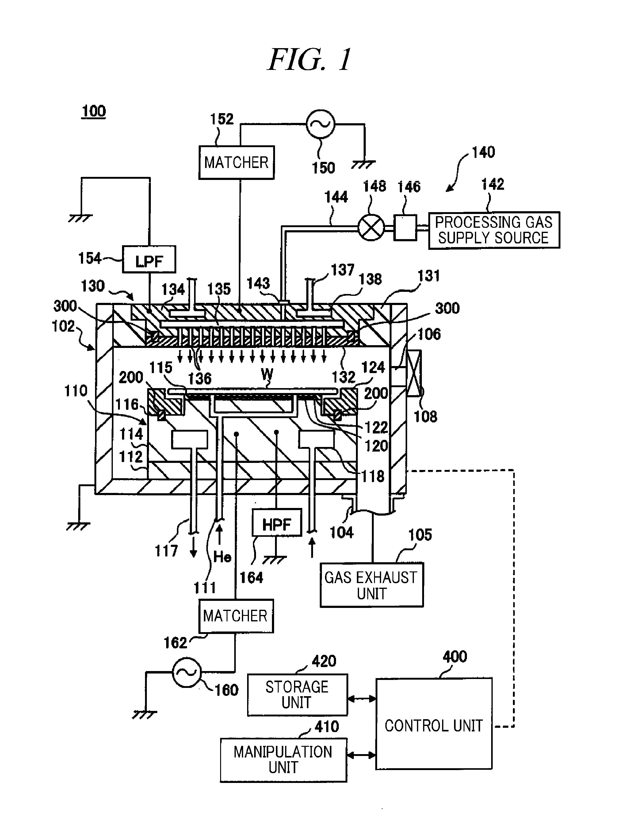
[0060]First, a schematic configuration of a substrate processing apparatus in accordance with a first embodiment of the present disclosure will be elaborated with reference to the relevant drawings. Here, the description will be provided for an example case of a plasma processing apparatus 100 of a single parallel plate type as a substrate processing apparatus. FIG. 1 is a longitudinal cross sectional view illustrating a schematic configuration of the plasma processing apparatus 100 in accordance with the first embodiment.

[0061]The plasma processing apparatus 100 includes a processing chamber 102 having a cylindrical processing vessel made of, e.g., aluminum of which surface is anodically oxidized (alumite treated). The processing chamber 102 is grounded. A substantially column-shaped mounting table 110 configured to mount a wafer W thereon is provided at a bottom of the processing chamber 102. The mounting table 110 includes a plate-shaped insulator 112 made of ceramic or the like ...

second embodiment

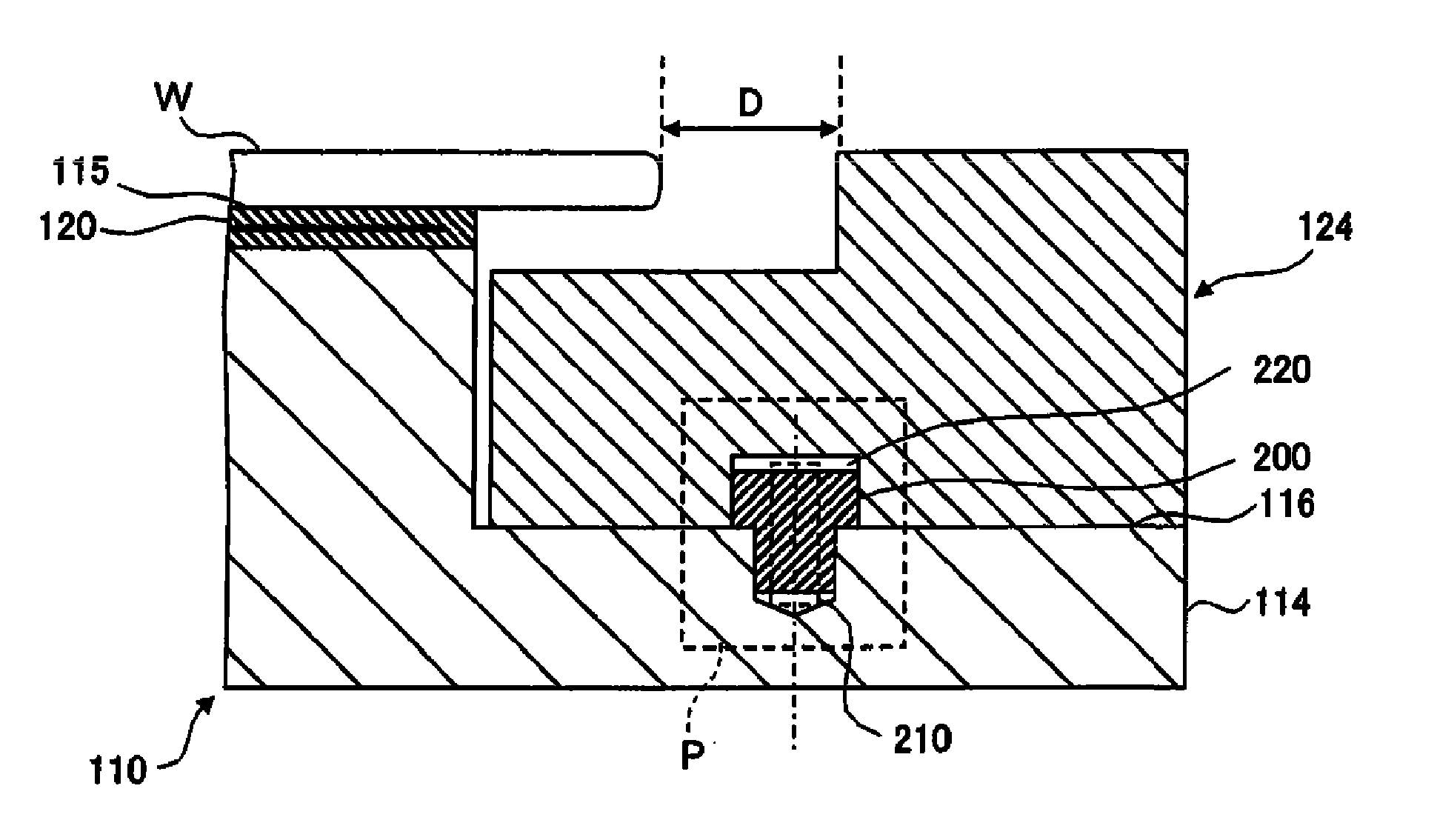
[0124]Hereinafter, a configuration example of a substrate processing apparatus in accordance with a second embodiment of the present disclosure will be described with reference to the accompanying drawings. Here, the description will be provided for a case of automatically installing and positioning a focus ring 124 by using the same positioning pins 200 as used in the first embodiment in a substrate processing apparatus including a single parallel plate type plasma processing apparatus and a transfer arm capable of loading and unloading a wafer W and the focus ring 124 to / from a processing chamber of the plasma processing apparatus. FIG. 12 is a longitudinal cross sectional view illustrating a configuration example of a plasma processing apparatus 101 in accordance with the second embodiment. FIG. 13 is a perspective view illustrating a configuration of a susceptor 114 shown in FIG. 12.

[0125]The plasma processing apparatus 101 illustrated in FIG. 12 is a parallel plate type plasma ...


PUM

PropertyMeasurementUnit
Temperatureaaaaaaaaaa
Vacuumaaaaaaaaaa

Abstract

Positioning accuracy of a component in a substrate processing apparatus can be improved higher than a conventional case without increasing the insertion accuracy of positioning pins into positioning holes. Provided is a substrate processing apparatus including a mounting table 110 including a susceptor 114 having a substrate mounting surface 115 on which a wafer W is mounted and a focus ring mounting surface 116 on which a focus ring 124 is mounted; a plurality of positioning pins 200 made of a material expandable in a diametric direction by heating. Each positioning pin is inserted into a positioning hole (first reference hole) formed in the focus ring mounting surface of the susceptor and into a positioning hole (second reference hole) formed in the focus ring, and expanded in the diametric direction by heating and fitted into the positioning holes, thus allowing a position of the focus ring to be aligned.

Description

CROSS-REFERENCE TO RELATED APPLICATION[0001]This application claims the benefit of U.S. Provisional Application Ser. No. 61 / 242,568 filed on Sep. 15, 2009, Japanese Patent Application No. 2009-183970 filed on Aug. 7, 2009, U.S. Provisional Application Ser. No. 61 / 360,694 filed on Jul. 1, 2010 and Japanese Patent Application No. 2010-133049 filed on Jun. 10, 2009, the entire disclosures of which are incorporated herein by reference.FIELD OF THE INVENTION[0002]The present disclosure relates to a substrate processing apparatus that processes a substrate such as a semiconductor wafer, a FPD (Flat Panel Display) substrate or a solar cell substrate and also relates to a method for positioning and installing a component such as a focus ring for use in the substrate processing apparatus.BACKGROUND OF THE INVENTION[0003]In a manufacturing process of a semiconductor device, a plasma etching process is repetitively performed to form a fine circuit pattern on a substrate such as a semiconductor...

Claims


Application Information

Patent Timeline
IPC IPC(8): C23C14/46B23P11/00
CPCH01J37/32623Y10T29/49826H01J37/32642
Inventor KOBAYASHI, YOSHIYUKI
Owner TOKYO ELECTRON LTD
Why Eureka
Try Eureka