
Gas-assisted laser ablation

a laser and laser technology, applied in the field of laser micromachining for fabricating microstructures, can solve the problems of poor process resolution, limited photochemical etching rate, concomitant thermal damage to nearby structures, etc., and achieve the effect of high ra

Active Publication Date: 2011-02-10
FEI CO
View PDF31 Cites 32 Cited by
  • Summary
  • Abstract
  • Description
  • Claims
  • Application Information

AI Technical Summary

Benefits of technology

[0013]An object of the invention is to provide an improved method for laser processing that prevents material redeposition during laser ablation but allows material to be removed at a high rate.

Problems solved by technology

The heat tends to diffuse to an area larger than the laser beam spot, making the resolution of the process poorer than the laser spot size and causing concomitant thermal damage to nearby structures.
Photochemical etching is limited to materials that are photochemically active.
Because electrons are much lighter than ions, electron beams are typically limited to removing material by inducing a chemical reaction between an etchant vapor and the substrate.
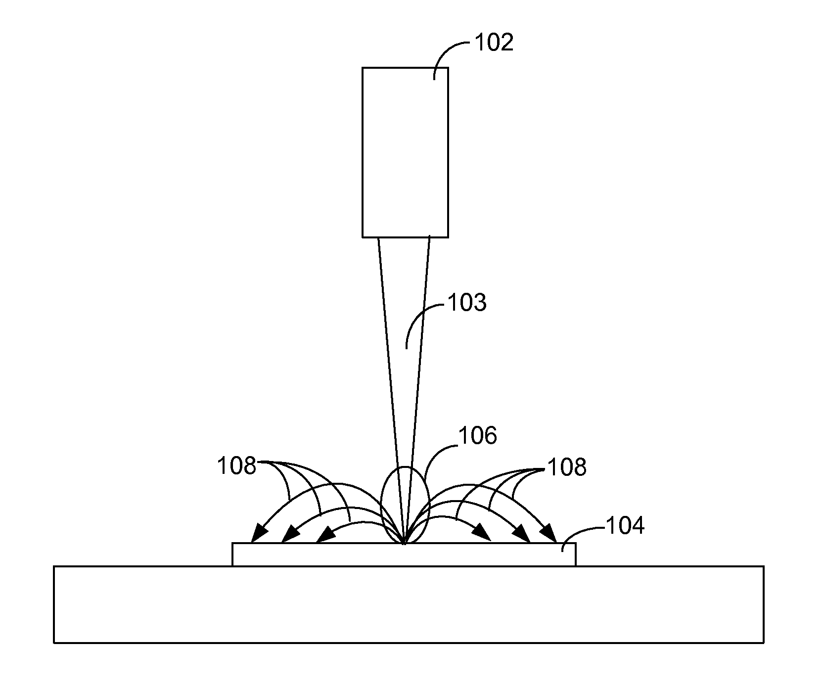
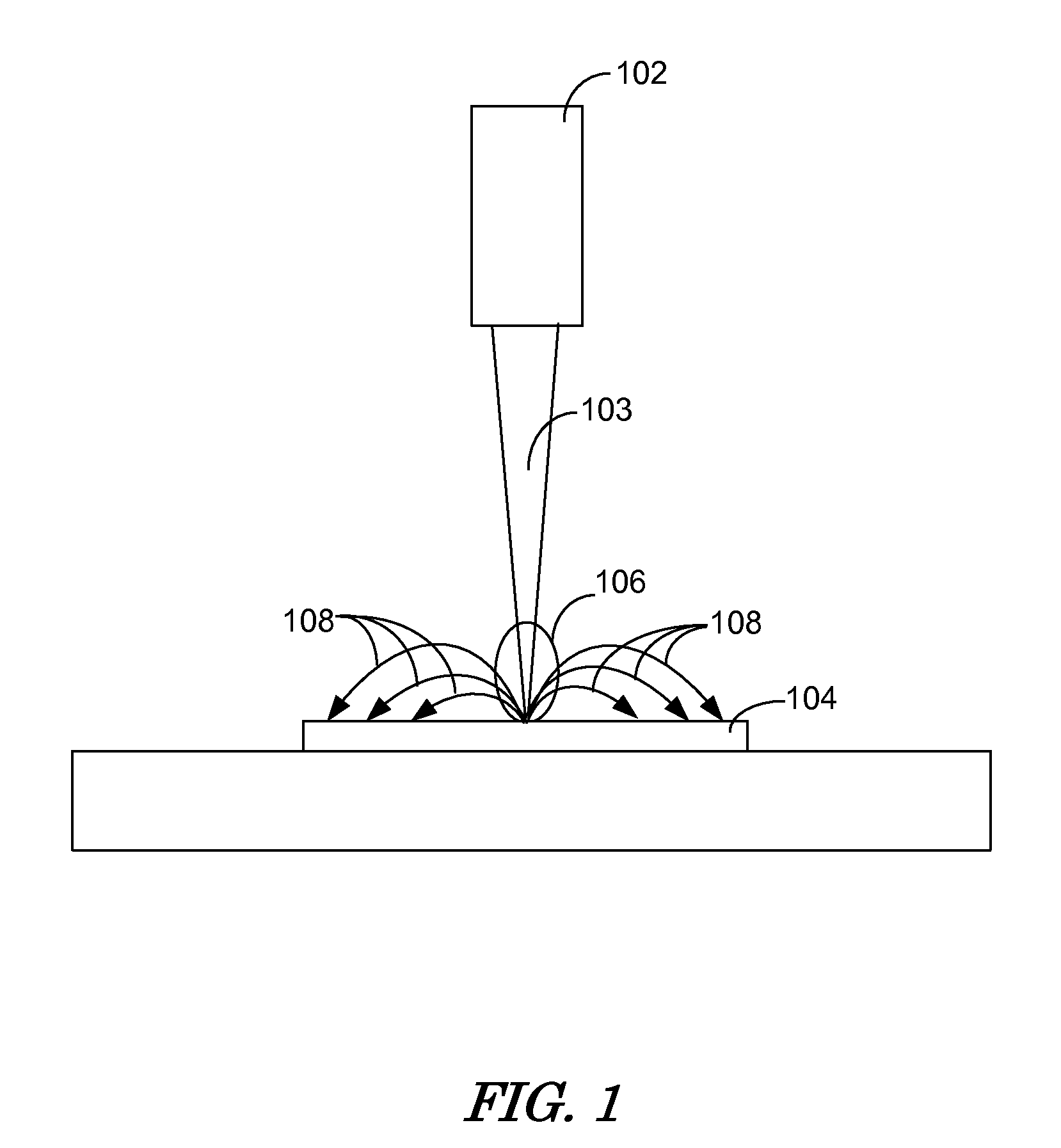
As the plasma cools, much of the solid debris 108 is redeposited on the workpiece surface, thus reducing the quality of the cut and decreasing the cutting efficiency since the debris must be removed again before the beam interacts with the workpiece surface.
Such secondary techniques are often not completely effective, and add significant complexity to the laser ablation system while decreasing cutting efficiency.
Unfortunately, even using the method described by Li, the material still redeposits onto the surface, some of it just travels farther away than it would at higher chamber pressure.
Like lasers, charged particle beam systems also have a problem with material redeposition.
If a charged particle beam, such as a focused ion beam (FIB), dwells too long in one location, all adsorbates will be dissociated or desorbed and the beam will begin to remove material by sputtering, with the resulting problem of material redeposition.
This increases processing time.
High concentrations (high gas pressures) of the precursor gas are not generally helpful because only a relatively small number of particles, forming a monolayer on the surface, adsorb onto the material surface at a time.

Method used


Image

  • Gas-assisted laser ablation
  • Gas-assisted laser ablation
  • Gas-assisted laser ablation

Examples


Embodiment Construction

[0024]Although those of ordinary skill in the art will readily recognize many alternative embodiments, especially in light of the illustrations provided herein, this detailed description is exemplary of the preferred embodiments of the present invention, the scope of which is limited only by the appended claims.

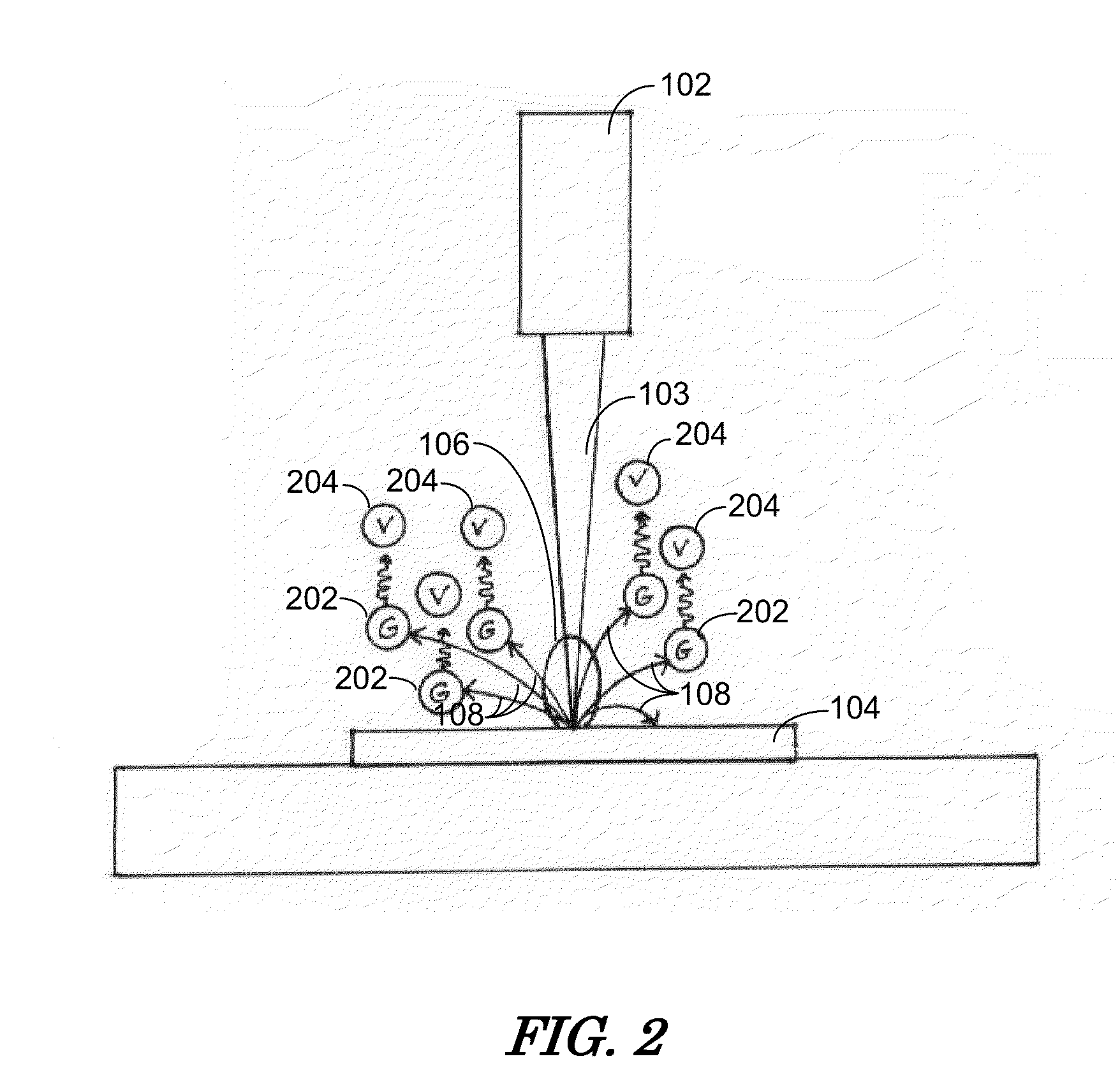
[0025]As described above, laser ablation is capable of rapidly removing a massive amount of material from a surface. Much of the material removed, however, is redeposited onto the surface, reducing the quality of the cut and decreasing cutting efficiency. As also described above, gas-assisted milling is used to reduce or eliminate redeposition in charged particle beam systems. Similar techniques have been employed with laser beam systems. Due to the relatively massive amount of material removed during laser ablation, the familiar mechanism of gas-assisted milling using a focused ion beam is of little or no benefit. A monolayer of an etchant gas adsorbed onto the sample surfac...


PUM

PropertyMeasurementUnit
energyaaaaaaaaaa
vacuum pressureaaaaaaaaaa

Abstract

An improved method for laser processing that prevents material redeposition during laser ablation but allows material to be removed at a high rate. In a preferred embodiment, laser ablation is performed in a chamber filled with high pressure precursor (etchant) gas so that sample particles ejected during laser ablation will react with the precursor gas in the gas atmosphere of the sample chamber. When the ejected particles collide with precursor gas particles, the precursor is dissociated, forming a reactive component that binds the ablated material. In turn, the reaction between the reactive dissociation by-product and the ablated material forms a new, volatile compound that can be pumped away in a gaseous state rather than redepositing onto the sample.

Description

[0001]This application claims priority from U.S. Provisional Application 61 / 232,780, filed Aug. 10, 2009, which is hereby incorporated by reference.TECHNICAL FIELD OF THE INVENTION[0002]The present invention relates generally to fabricating microstructures by laser micromachining, and more particularly, to laser micromachining using an etchant gas.BACKGROUND OF THE INVENTION[0003]Removing material from a substrate to form microscopic or nanoscopic structures is referred to as micromachining, milling, or etching. Lasers beams and charged particle beams are two particular technologies used for micromachining. Each has advantages and limitations in various applications.[0004]Laser systems use several different mechanisms for micromachining. In some processes, the laser is used to supply heat to a substrate to induce a chemical reaction. The reaction occurs only in the heated areas. The heat tends to diffuse to an area larger than the laser beam spot, making the resolution of the proces...

Claims


Application Information

Patent Timeline
Patent Type & Authority Applications(United States)
IPC IPC(8): B29C35/08
CPCB23K26/0635B23K26/12B23K26/126B23K26/36B23K26/127B23K26/16B23K26/0624B41M5/24B29C35/08
Inventor TOTH, MILOSSTRAW, MARCUS
Owner FEI CO
Learn More