Control apparatus for electric rotating machine

a control apparatus and electric rotating machine technology, applied in the direction of dynamo-electric converter control, motor/generator/converter stopper, dynamo-electric gear control, etc., can solve the problem of difficulty in controlling the output current at the command value in the overmodulation range in which the modulation index exceeds 1

Active Publication Date: 2011-02-10
DENSO CORP
View PDF4 Cites 24 Cited by
  • Summary
  • Abstract
  • Description
  • Claims
  • Application Information

AI Technical Summary

Benefits of technology

[0013]According to the present invention, there is provided a control apparatus for an electric rotating machine capable of appropriately performing the model predictive control even in the overmodulation range.

Problems solved by technology

However, in the control apparatus which performs the model predictive control, although the output current of an inverter can be controlled at a command current within the range in which the modulation index is smaller than 1, that is, an average amplitude between output lines of the power converter circuit is smaller than the voltage of the DC power source, it is difficult to control the output current at the command value in the overmodulation range in which the modulation index exceeds 1 due to the constraint depending on the input voltage of the inverter.

Method used


Image

  • Control apparatus for electric rotating machine
  • Control apparatus for electric rotating machine
  • Control apparatus for electric rotating machine

Examples


first embodiment

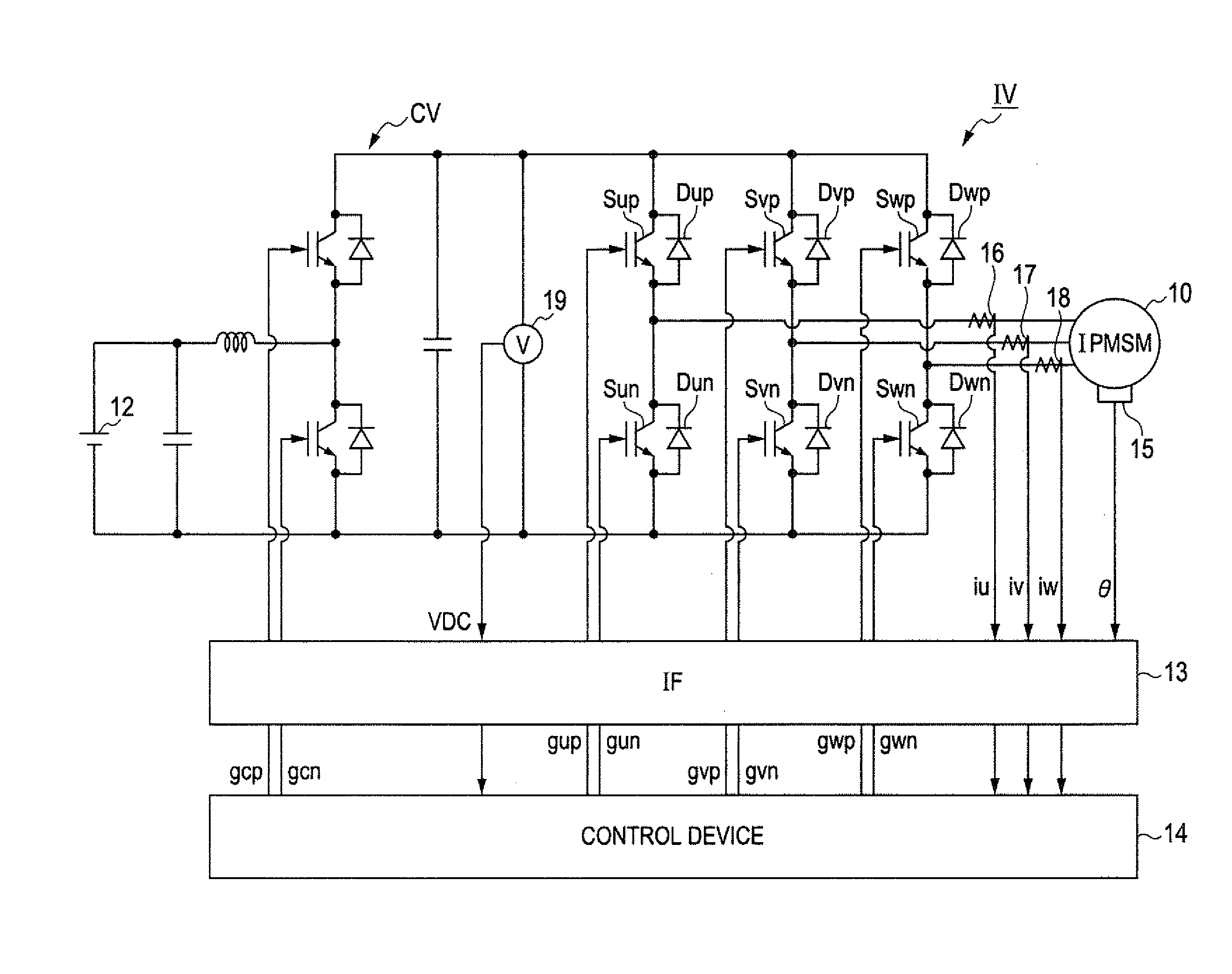
[0040]FIG. 1 is a diagram showing the overall structure of a control system for a motor-generator 10 mounted on a hybrid vehicle, the system including a control apparatus according to a first embodiment of the invention. The motor-generator 10 is a salient-pole type electric rotating machine which operates as a three-phase permanent magnet synchronous motor. That is, the motor-generator 10 is an IPMSM (Interior Permanent magnet Synchronous Motor).

[0041]The motor-generator 10 is connected to a high voltage battery 12 through an inverter IV and a step-up converter CV. The step-up converter CV steps up the output voltage of the high-voltage battery 12 (288 V, for example) up to a predetermined voltage (666 V, for example). The inverter IV is constituted of a series connection of switching elements Sup and Sun, a series connection of switching elements Svp and Svn, and a series connection of switching elements Swp and Swn, these series connections being connected to the U, V and W phase...

second embodiment

[0073]Next, a second embodiment of the invention is described with particular emphasis on the difference with the first embodiment.

[0074]In the second embodiment, a sub-feedback control is performed to control the current flowing through the motor-generator 10 at the command current set by the feedback control of the average value of, magnitude of the of the output voltage.

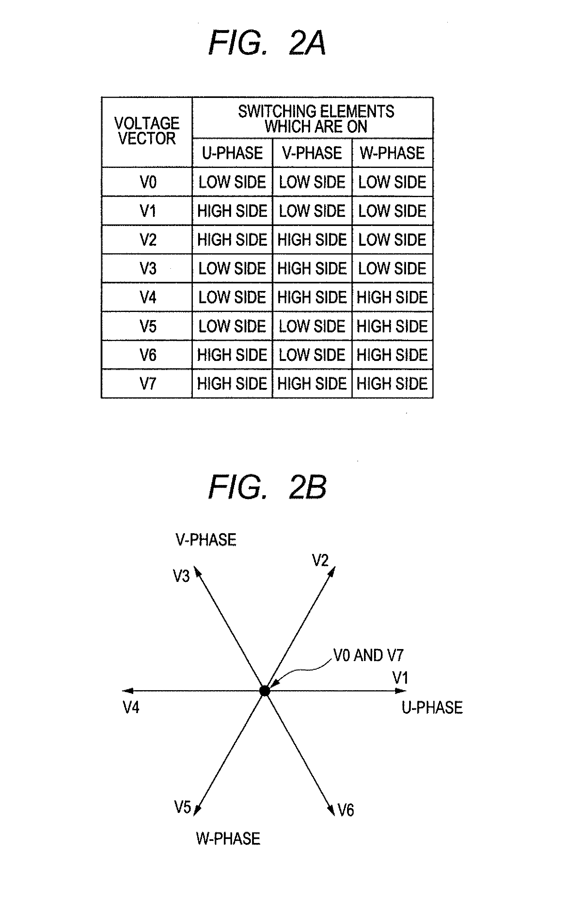
[0075]FIG. 5 is a functional block diagram explaining the process of model predictive control performed in this embodiment. In FIG. 5, the same reference numerals or characters identical to those shown in FIG. 3 represent the same components.

[0076]As shown in FIG. 5, a deviation calculating section 80 calculates the d-axis deviation Δid by subtracting the predicted current ide from the command current idr. A deviation calculating section 82 calculates the q-axis deviation Δiq by subtracting the predicted current iqe from the command current iqr. A deviation norm calculating section 84 receives the d-axis deviation...

third embodiment

[0081]Next, a third embodiment of the invention is described with particular emphasis on the difference with the first embodiment.

[0082]In the third embodiment, sub-feedback control is performed by use of a proportional element and an integral element to control the current flowing through the motor-generator 10 at the command current set by the feedback control of the average value of magnitude of the output voltage.

[0083]FIG. 6 is a functional block diagram explaining the process of model predictive control performed in this embodiment. In FIG. 6, the same reference numerals or characters identical to those shown in FIG. 3 represent the same components.

[0084]As shown in FIG. 6, the difference between the average voltage vector norm Ne and the norm target value Nr is multiplied by the integral gain Ki2 at an integral gain setting section 90. The output of the deviation norm calculating section 84 is multiplied by the integral gain Ki1 at an integral gain setting section 92. The out...


PUM


Abstract

The control apparatus controls a controlled variable of the electric rotating machine by manipulating an output voltage of a power converter circuit including switching elements operated at a set modulation index to connect positive and negative terminals of a DC power source to corresponding terminals of the electric rotating machine. The control apparatus includes a prediction section configured to predict the controlled variable for each of a plurality of cases where the power converter circuit is set in a corresponding one of a plurality of predetermined operating states, a manipulation section configured to determine one of the predetermined operating states depending on a result of evaluation by an evaluation function, and set the converter circuit to the determined operating state, and a feedback control section configured to feedback-control the output voltage of the power converter circuit at a target value by manipulating the input parameters of the evaluation function.

Description

[0001]This application claims priority to Japanese Patent Application No. 2009-182424 filed on Aug. 5, 2009, the entire contents of which are hereby incorporated by reference.BACKGROUND OF THE INVENTION[0002]1. Field of the Invention[0003]The present invention relates to a control apparatus for an electric rotating machine, the control apparatus being configured to control the controlled variables of the electric rotating machine by adjusting the output voltage of a power converter circuit including switching elements which are operated to connect positive and negative terminals of a DC power source to corresponding terminals of the electric rotating machine.[0004]2. Description of Related Art[0005]Such control apparatuses include the one which performs triangular wave comparison PWM control in which, in order to feedback-control the currents flowing through the respective phases of a three-phase motor at their command values, command voltages of the respective phases are calculated...

Claims


Application Information

Patent Timeline
Patent Type & Authority Applications(United States)
IPC IPC(8): H02P27/06H02M7/48H02M7/5387H02P21/00H02P21/13H02P21/14H02P21/22H02P23/14H02P27/04H02P27/08H02P29/00
CPCH02P21/0003H02P2201/07H02P21/0089
Inventor TAKAHASHI, TOMOYA
Owner DENSO CORP
Why Eureka
Try Eureka