Pulse modulated RF power control method and pulse modulated RF power supply device

a power supply device and pulse technology, applied in pulse manipulation, pulse technique, dc-ac conversion without reversal, etc., can solve the problems of unstable output power, further fluctuations of reflected power, unstable output power, etc., to facilitate plasma generation within the chamber, enhance both process homogeneity, and stabilize the plasma load

Active Publication Date: 2011-02-10
KYOSAN ELECTRIC MFG CO LTD
View PDF5 Cites 40 Cited by
  • Summary
  • Abstract
  • Description
  • Claims
  • Application Information

AI Technical Summary

Benefits of technology

[0076]According to an aspect of the present invention, the power amplitude of the output power is stably controlled, thereby stabilizing plasma density and plasma atmosphere on the load side, and enhancing both the process homogeneity obtained by the plasma treatment and a product quality obtained by the process.
[0077]According to an aspect of the present invention, the average reflected power is suppressed against the increase of the reflected power, so as to protect the power supply device, while the power amplitude (peak forward power) of the forward power is maintained, thereby eliminating the need for unrequisite matching operations of the matching box, and stabilizing the plasma load.
[0078]Furthermore, according to an aspect of the present invention, generation of plasma within the chamber is facilitated at the time of process start on the load side.
[0079]As described above, according to the pulse modulated RF power control method and the pulse modulated RF power supply device of the present invention, it is possible to control the power amplitude (peak power) of the output power to be constant against the power fluctuations in the pulse power control, thereby avoiding effects on the load, which is caused by the fluctuation of the power amplitude of the output power.

Problems solved by technology

Fluctuations of the peak forward power may produce problems, such as rendering output power unstable and affecting a process that is carried out in a chamber on the load side.
This fluctuation of the matching point destabilizes the impedance in a plasma chamber to process the plasma on the load side, and causes further fluctuations of the reflected power.
Consequently, the output power becomes unstable.
In addition, when the peak forward power fluctuates, plasma density and plasma atmosphere within the chamber are varied simultaneously, and accordingly, the homogeneity and yield of a process performed in the chamber may be affected adversely.
During the operation of the process performed by the plasma on the load side, if outputting of the forward power is lowered to protect the RF power supply device, in the case where the peak reflected power is increased in the chamber due to a variation of the impedance, there is a problem that lowering of the forward power may cause a loss of plasma activation, interrupt the process development, and affect a product quality.
Here, a problem is pointed out that if the output of the forward power is lowered so as to protect the RF power supply device from the increase of the reflected power, ignition of the plasma may become more difficult.
Therefore, if the reflected power is increased, the amount of the power supplied to the load is lowered, and a plasma state within the chamber is changed, thereby causing the load impedance to fluctuate.
This fluctuation may cause a deviation from the matching state, failing to keep the plasma, and accordingly, the plasma disappears.
Furthermore, when the amount of the power supplied to the load becomes unstable and the load side impedance fluctuates, a target point of the matching also becomes unstable.
Accordingly, a target position of a variable impedance element of the matching circuit may also become unstable, and there is a possibility that the variable impedance element causes a hunting phenomenon.
Such hunting phenomenon during the process of matching as described above may operate only a part of the variable impedance element of the matching circuit, and it may shorten a lifetime of the variable impedance element.
Therefore, power amplitude of the output power becomes unstable, causing problems such as fluctuations of the plasma state within the chamber.

Method used


Image

  • Pulse modulated RF power control method and pulse modulated RF power supply device
  • Pulse modulated RF power control method and pulse modulated RF power supply device
  • Pulse modulated RF power control method and pulse modulated RF power supply device

Examples


first embodiment

Configuration and Control when Forward Power is Assumed as a Control Target

[0151]Next, as a first embodiment of the present invention, a configuration and control operations will be explained with reference to FIG. 6 to FIG. 8, as to the case where forward power is assumed as a control target.

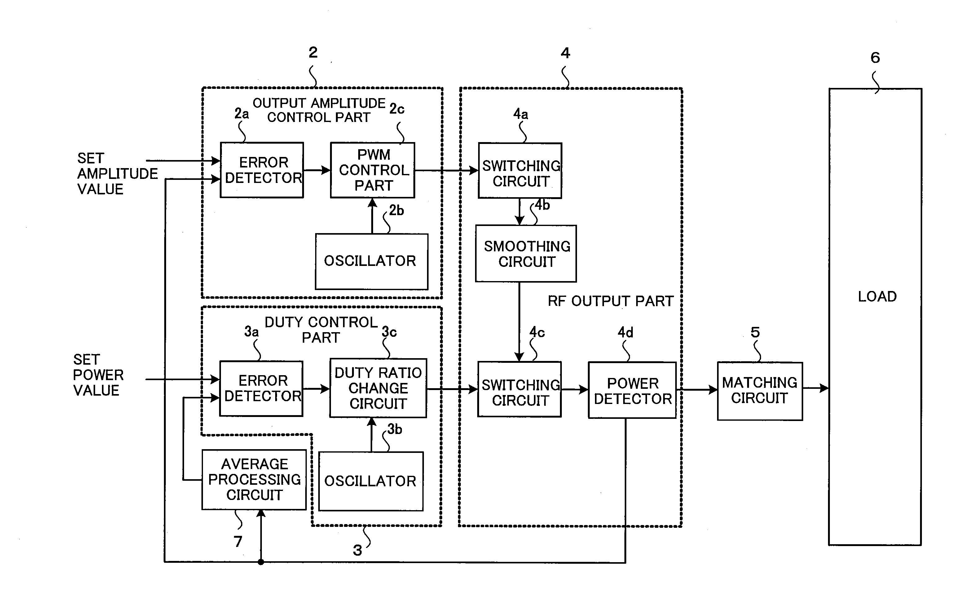
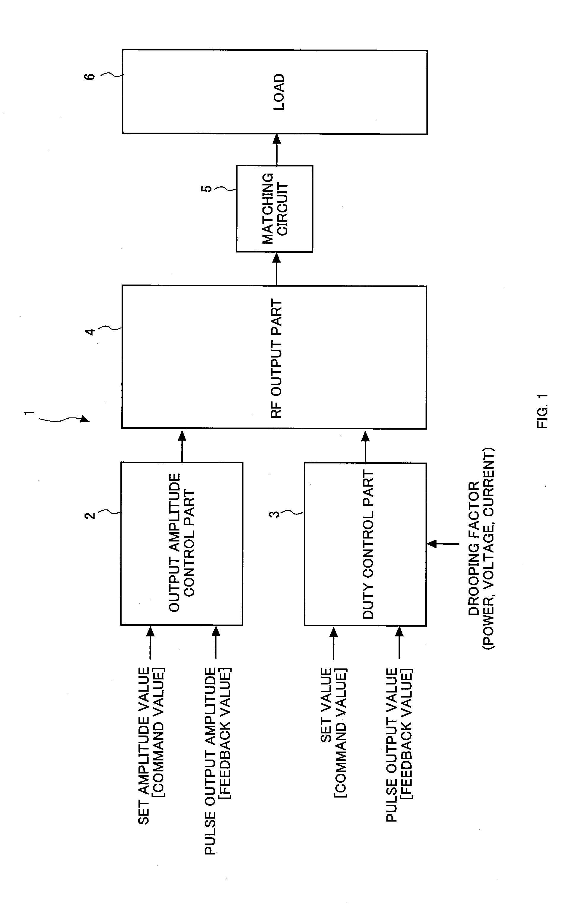
[0152]FIG. 6 is a diagram for explaining a configuration example in the case where the forward power is assumed as the control target. In FIG. 6, a configuration of the pulse modulated RF power supply device 1A is almost the same as the configuration as shown in FIG. 1, incorporating a peak forward power control part 2A as the output amplitude control part 2 for controlling amplitude of a pulse output, an average forward power control part 3A as the duty control part 3 for controlling a duty ratio of the pulse output, and an RF output part 4A as the RF output part 4 for outputting an RF output of the pulse output. The RF output part 4A outputs the RF output to a load.

[0153]The peak forward powe...

second embodiment

Control Example when Peak Reflected Power is Increased

[0166]Next, as a second embodiment of the present invention, a control of the forward power will be explained with reference to FIG. 9 to FIG. 12, as to the case where the peak reflected power is increased.

[0167]In FIG. 9, a configuration of the pulse modulated RF power supply device 1B is almost the same as the configuration as shown in FIG. 6, incorporating a peak forward power control part 2B for controlling an amplitude of a pulse output, an average forward power control part 3B for controlling a duty ratio of the pulse output, an RF output part 4B for outputting an RF output of the pulse output, and an average processing part 7B. The RF output part 4B is provided with an RF output circuit 4d0, a forward power detecting part 4d2, a reflected power detecting part 4d3 for detecting peak reflected power, and a directional coupler 4d1 for achieving separation between the peak forward power and the peak reflected power to retrieve...

third embodiment

Configuration and Control of Load Power Control

[0179]Next, as a third embodiment of the present invention, a configuration of the load power control and control operations thereof will be explained with reference to FIG. 13 to FIG. 16.

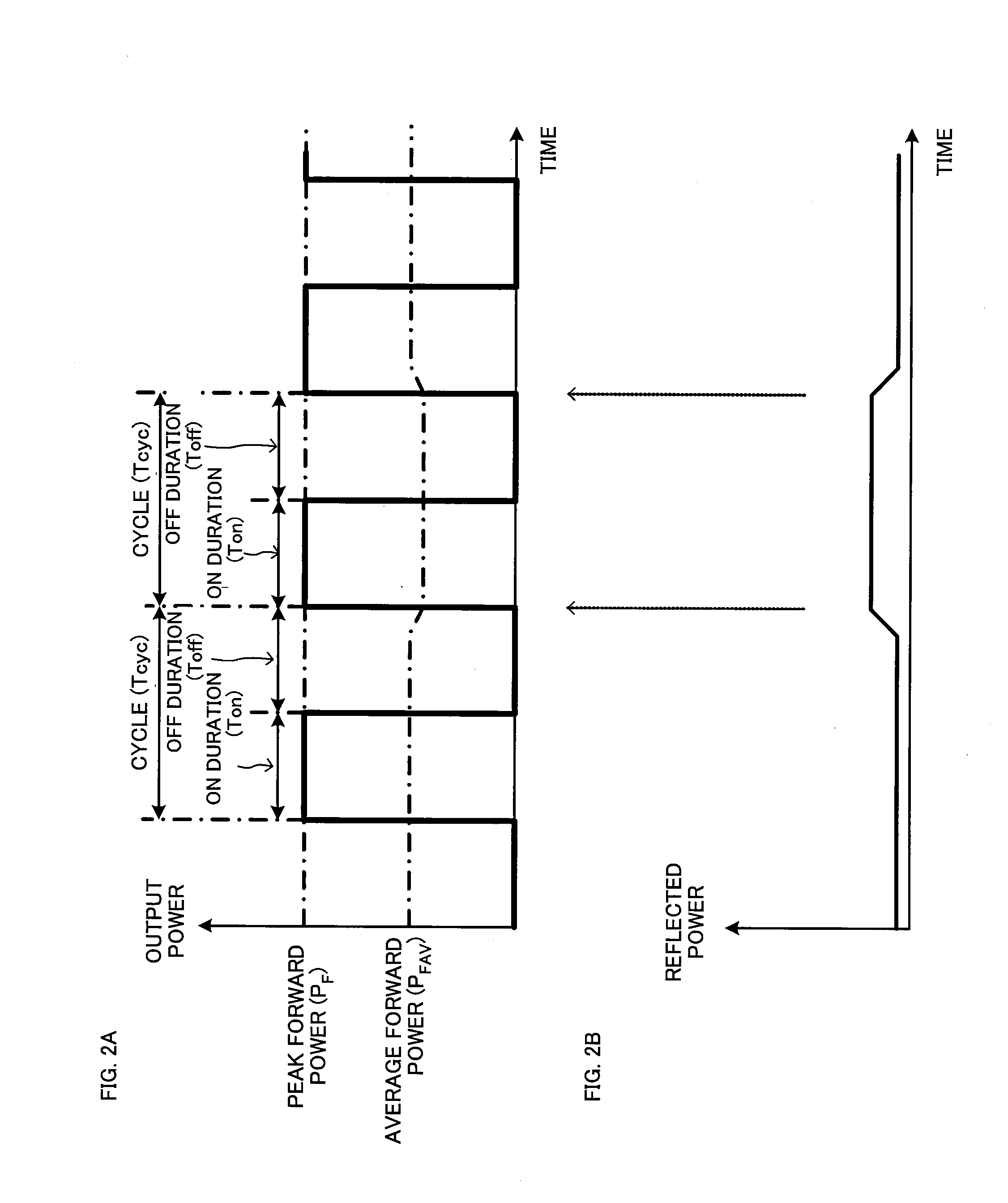
[0180]The load power is obtained by subtracting reflected power from forward power, and the load power control controls average load power which is substantially supplied from the pulse modulated RF power supply device to the load, thereby stabilizing the peak forward power output.

[0181]The load power control assumes the peak forward power as a control target as to the pulse output in the output amplitude control, assumes the average load power as a control target as to the pulse output in the duty control step. The output amplitude control performs constant amplitude control so that an amplitude value of the peak forward power becomes constant. The duty control controls the average load power, by performing the constant power control so that an averag...


PUM


Abstract

The pulse modulated RF power control method includes an output amplitude control step for controlling amplitude of a pulse output, and a duty control step for controlling a duty ratio of the pulse output. The output amplitude control step performs a constant amplitude control to control an amplitude value of the pulse output so that the amplitude value becomes equal to a set amplitude value. The constant amplitude control according to the output amplitude control, for instance, gives a feedback of the amplitude value of the pulse output outputted by the power control, obtains a difference value between the feedback value and the set amplitude value, and controls the amplitude value of the pulse output so that the difference value becomes zero.

Description

FIELD OF THE INVENTION[0001]The present invention relates to a radio-frequency (RF) power control method and an RF power supply device, and in particular, it relates to pulse power modulation for modulating power with a pulse-like waveform which is supplied to a load.DESCRIPTION OF THE RELATED ART[0002]As a method for controlling RF power to be supplied to a load, there are known a method for performing a control to establish constant forward power outputted from the RF power supply device (PF control) and a method for performing a control to establish constant load power which is obtained by subtracting reflected power from the forward power (PL control), as disclosed in the Japanese Unexamined Patent Application Publication No. 2007-087908 (see paragraphs 0002 to 0009, 0026, and 0027) and the Japanese Unexamined Patent Application Publication No. 2009-111940 (see paragraphs 0002 and 0011), which will be referred to as “patent document 1” and “patent document 2”, respectively.[0003...

Claims


Application Information

Patent Timeline
Patent Type & Authority Applications(United States)
IPC IPC(8): H03K7/10
CPCH01J37/32082H01J37/32183H03F3/191H02M2001/007H03K7/08H03K7/10H02M7/48H03F3/217H02M1/007H03K5/00H05H1/46H01L21/205H03K5/156
Inventor YUZURIHARA, ITSUOHATA, YOSHIHISA
Owner KYOSAN ELECTRIC MFG CO LTD
Why Eureka
Try Eureka