Panel antenna having sealed radio enclosure

a radio enclosure and antenna technology, applied in the field of panel antennas, can solve the problem that the sink on the rear panel may dissipate heat from additional active electronics

Active Publication Date: 2011-02-10
PROCOMM INT PTE LTD
View PDF10 Cites 66 Cited by
  • Summary
  • Abstract
  • Description
  • Claims
  • Application Information

AI Technical Summary

Problems solved by technology

The heat sink on the rear panel may dissipate heat from additional active electronics, such as a communications hub or calibration radio.

Method used


Image

  • Panel antenna having sealed radio enclosure
  • Panel antenna having sealed radio enclosure
  • Panel antenna having sealed radio enclosure

Examples


Embodiment Construction

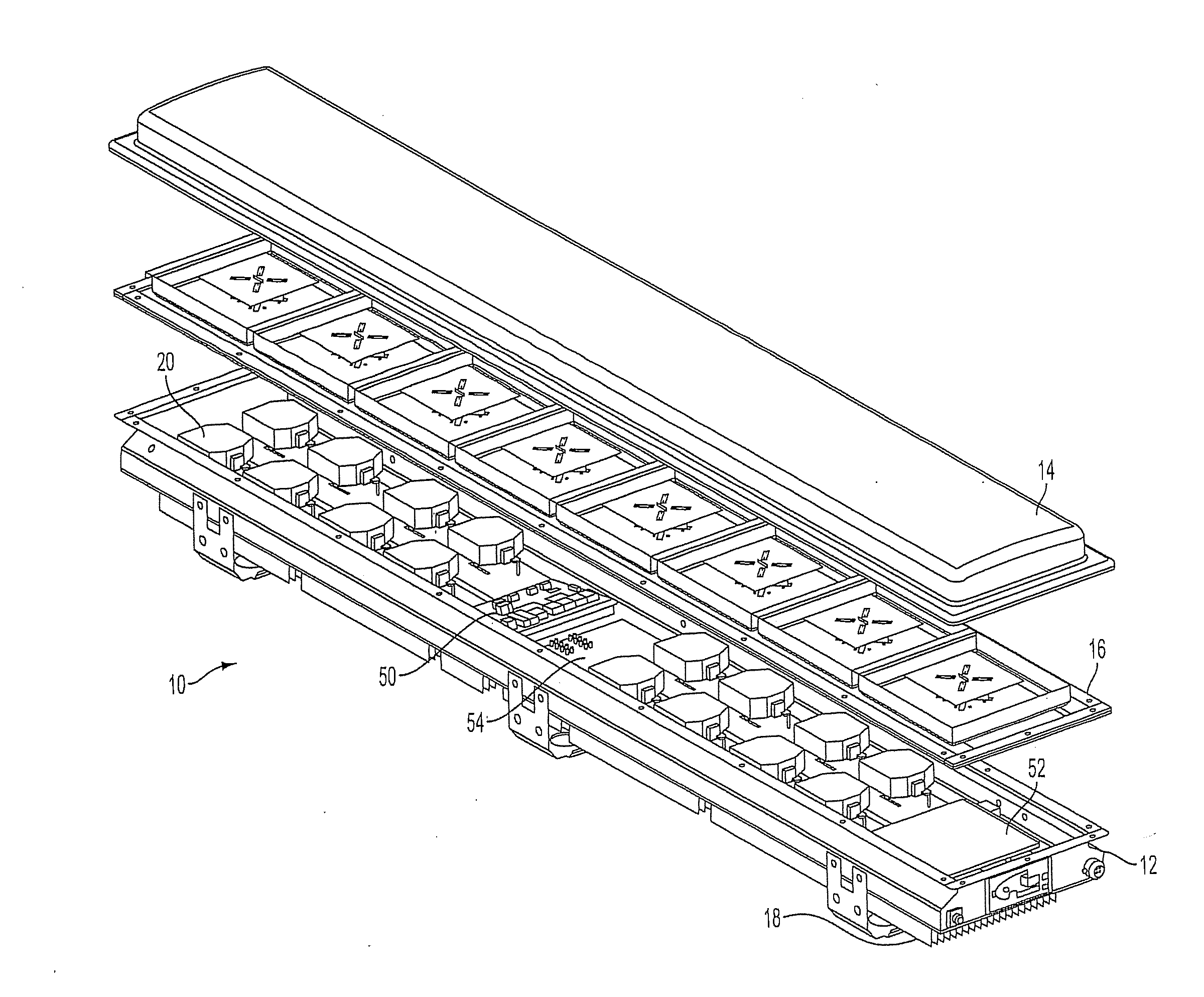
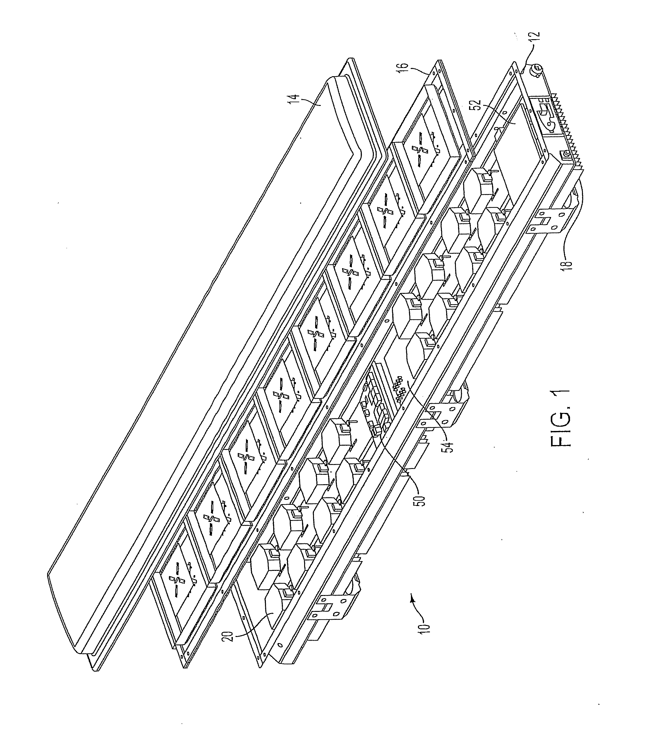
[0023]Referring to FIG. 1, in one example, a Panel Antenna 10 comprises an enclosure 12, internal cover 14, radome 16 and rear heat sinks 18. As described in more detail below, the enclosure 12 may be formed from sheet metal. The Panel Antenna 10 may include a plurality of micro radios 20 mounted within the enclosure 12. The micro radios 20 may be thermally coupled to the rear heat sinks 18. In one aspect of the invention, described in more detail below, the internal cover 14 may include a plurality of RF modules 24.

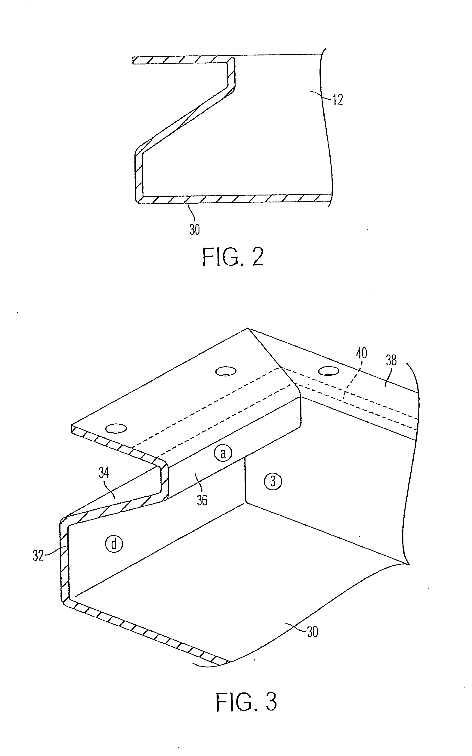
[0024]Referring to FIGS. 2 and 3, the enclosure 12 comprises a rear panel 30, a lower side wall 32, an angled side wall 34, an upper side wall 36, and a flange 38. In one example, lower side wall 32 and upper side wall 36 are perpendicular to rear panel 30 and flange 38 is parallel to the rear panel 30. Angled side wall 34 is angled toward the interior of the enclosure. The rear panel 30, side walls 32, 34, 36 and flange 38 may be formed from sheet metal. Corners, formed...


PUM


Abstract

A panel antenna having an enclosure, an internal cover, one or more micro radios and RF modules, and a radome is provided. The enclosure may include a rectangular rear panel, side walls with an interior surface to mount micro radios and an external surface to receive heat sinks, and a hinged front cover providing an internal cover. The internal cover may also have a plurality of RF radiating modules fastened thereto. The internal cover may also provide environmental sealing and electromagnetic shielding. The plurality of micro radios are located inside the cavity of the enclosure, and each micro radio is coupled to an RF radiating module. The micro radios may be mounted inside the enclosure on the side walls. The radome encloses the RF radiating modules. The radome may be mounted to the internal seal. Additionally, the panel antenna may further include a heat sink mounted on an exterior side of the rear panel. The heat sink on the rear panel may dissipate heat from additional active electronics, such as a communications hub or calibration radio. The micro radios and active electronics may be mounted such that the heat sinks dissipate heat generated by the micro radios.

Description

FIELD OF THE INVENTION[0001]The field of the invention relates generally to panel antennas used in communications applications. More particularly, the field of the invention relates to arrangements of passive and active antenna components in an multiple radiating element panel antenna.BACKGROUND OF THE INVENTION[0002]A typical known Cellular Telephone Base Station System comprises several elements, including one or more panel antennas, each panel antenna comprising an array of radiating elements mounted at an elevation above the ground, and base station electronics mounted remotely from the antenna arrays. The known antenna arrays typically include a plurality of radiating elements and a feed network. The radiating elements and feed network may be mounted on a panel antenna plate. See, e.g., U.S. Pat. No. 6,034,649, titled Dual Polarized Base Station Antenna. In some antennas, a ground plane for the radiating elements may be used as a part of the antenna structure. In some known pan...

Claims


Application Information

Patent Timeline
Patent Type & Authority Applications(United States)
IPC IPC(8): H01Q1/24
CPCH01Q1/02H01Q1/246H01Q1/42H01Q21/12H01Q19/10H01Q21/06H01Q9/0407
Inventor RODGER, DEREKFERRIS, MATTHEW
Owner PROCOMM INT PTE LTD
Why Eureka
Try Eureka