Compact HVAC system for a motor vehicle

a hvac system and motor vehicle technology, applied in the direction of cooling fluid circulation, domestic cooling apparatus, lighting and heating apparatus, etc., can solve the problems of high-volume components of air conditioning as known from stationary air conditioning units that cannot be used, assembly is expensive, and potential leakage points that could only be corrected with very much time and cost consumed

a hvac system and motor vehicle technology, applied in the direction of cooling fluid circulation, domestic cooling apparatus, lighting and heating apparatus, etc., can solve the problems of high-volume components of air conditioning as known from stationary air conditioning units that cannot be used, assembly is expensive, and potential leakage points that could only be corrected with very much time and cost consumed

US20110036117A1Inactive Publication Date: 2011-02-17HANON SYST

Image

  • Compact HVAC system for a motor vehicle
  • Compact HVAC system for a motor vehicle
  • Compact HVAC system for a motor vehicle

Examples


Embodiment Construction

[0088]The following detailed description and appended drawings describe and illustrate various embodiments of the invention. The description and drawings serve to enable one skilled in the art to make and use the invention, and are not intended to limit the scope of the invention in any manner. In respect of the methods disclosed, the steps presented are exemplary in nature, and thus, the order of the steps is not necessary or critical.

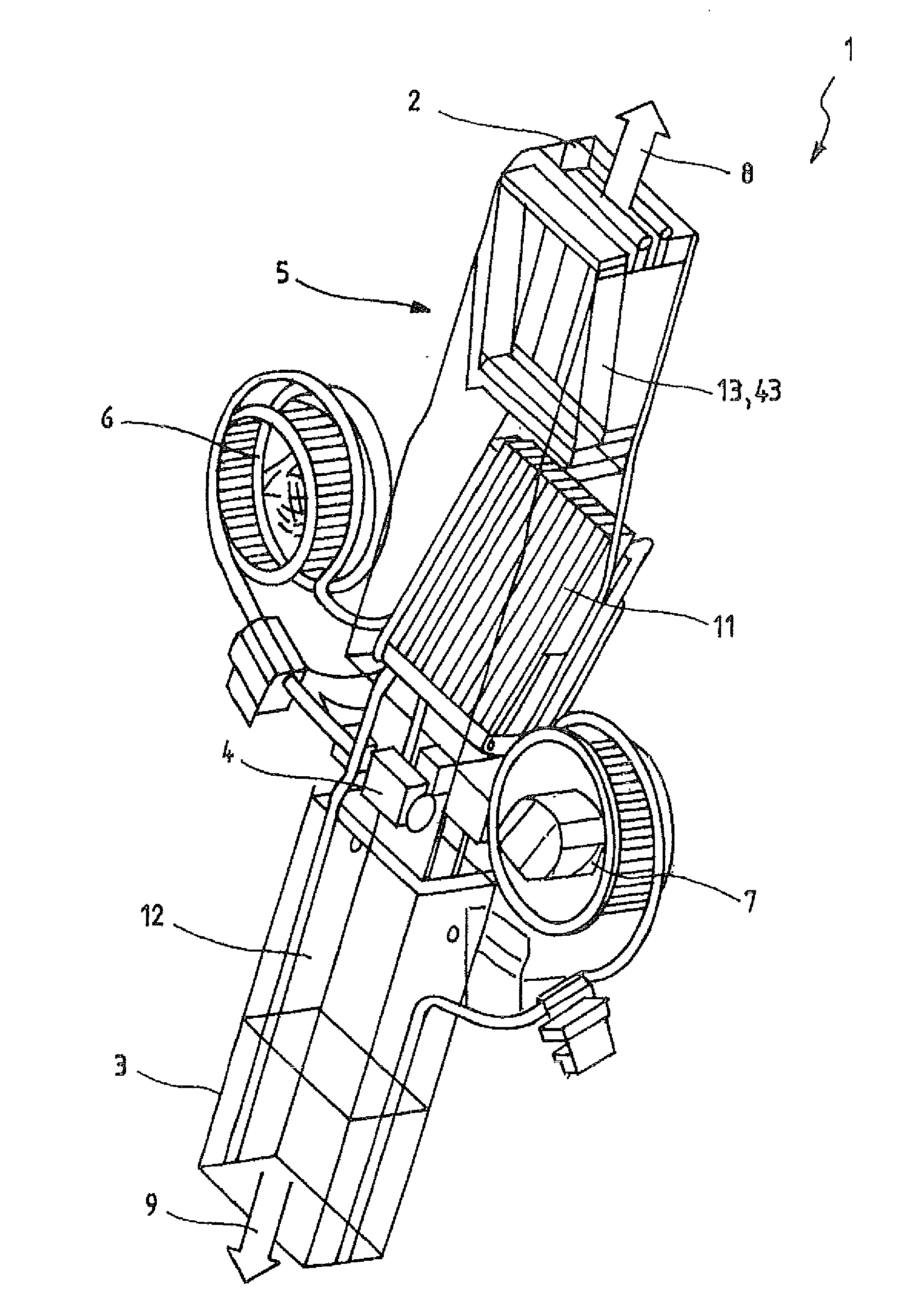
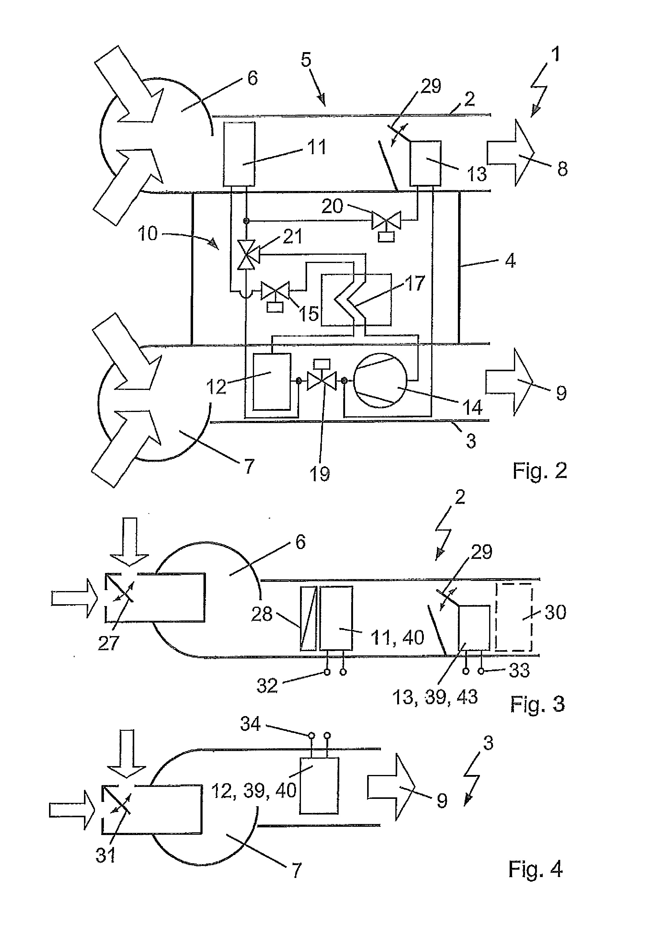
[0089]In FIG. 1, the compact vehicle HVAC system 1 according to the invention with a linear arrangement of the flow channels is shown. The casings of the evaporator unit 2 and the condenser unit 3, each forming a flow channel of a fresh / recirculated air system, have a rectangular flow cross-section in the range of the channels and are displaced with their faces to each other, linearly after each other. The faces displaced to each other are established closed, whereas the respective opposite sides, as sides of air exit, are established open. In an alte...


PUM


Abstract

The invention relates to a compact vehicle HVAC system including an evaporator unit, a condenser unit, and a component unit, as well as a refrigerant circuit. The evaporator unit and the condenser unit each are provided with air-passed heat exchangers and a fan in a casing. Further circuit components are displaced within the component unit. The casings of the evaporator unit, the condenser unit, and the component unit advantageously establish a connected compact casing arrangement. The heat exchangers are displaced within the compact casing arrangement. The refrigerant circuit is established for a combined refrigeration plant and heat pump operation as well as an afterheating operation, whereby in the afterheating operational mode the heating power of the afterheater established as condenser / gas cooler and the cooling power of the evaporator are controllable independently of each other.

Description

CROSS-REFERENCE TO RELATED APPLICATION[0001]This application claims priority to German Patent Application Serial Number DE 10 2009 028 522.9 filed Aug. 13, 2009, the entire disclosure of which is hereby incorporated herein by reference.FIELD OF THE INVENTION[0002]The invention relates to a compact vehicle HVAC system including different units. The units establish a connected, compact casing arrangement. The compact vehicle HVAC system is provided for the combined refrigeration plant and heat pump operation as well as an afterheating operation for heating, cooling and dehumidifying of the air to be conditioned for the passenger compartment. Also, the invention relates to a process for operating the HVAC system.BACKGROUND OF THE INVENTION[0003]Generally, in recent motor vehicles, it is demanded of the technical components because of their great number that the volume of the single components and the placement relative to each other be optimized in order to realize the desired function...

Claims


Application Information

Patent Timeline
17 Feb 2011
Publication
US20110036117A1
IPC
F25D17/06; F25B41/00
CPC
B60H1/00028; B60H1/00021; B60H2001/00085; B60H1/00921
Inventors
FROHLING, JORN; GRAAF, MARC