Illumination button, illumination switch assembly, and button structure having quickly removable button cap

a button and button technology, applied in the field of illumination switch assembly, can solve the problems of user's inability to quickly recognize the position of the button and the button symbol on the button, user's inability to correctly operate the button, and relatively complicated assembly process of the button module, so as to facilitate re-work or replace the button cap

Inactive Publication Date: 2011-02-17
WISTRON CORP
View PDF3 Cites 50 Cited by
  • Summary
  • Abstract
  • Description
  • Claims
  • Application Information

AI Technical Summary

Benefits of technology

[0021]The clamping members fix the connecting members in a clamping manner, such that a welding tool or the like is not required for fixing the connecting members. At the same time, the connecting members may be detached from the clamping members to remove the button cap, thereby facilitating re-work or replacement of the button cap.

Problems solved by technology

When an electronic device is operated in poor illumination environment, the user is usually unable to recognize the position of the button and the button symbol on the button rapidly.
Therefore, the user cannot correctly operate the button.
The light guide element or diffusion piece makes the assembly process of the button module relatively complicated.
However, the additional pigment easily drops off when the button cap is pressed and rubbed, such that the button symbol becomes obscure and indistinguishable.
A disadvantage of the welding is that re-work or replacement of the button cap is not convenient, and welding tools are required for installing the button cap.
If the button cap is found damaged or with a poor quality outside the factory, the button cap is usually unable to be replaced separately and the entire case has to be replaced.
As the button cap is often an element that is damaged most easily or is of poor quality, the button cap fixed through welding increases the cost of subsequent maintenance or quality control.
In the prior art, in order to illuminate a button cap effectively, a light guide element or a diffusion piece usually is required to be disposed below the button cap, such that an assembly process of the button is relatively complicated.
At the same time, since an illuminating light source cannot irradiate a center of the button cap directly, an illumination effect is relatively poor.
Further, the button cap having a partial light-pervious area is fabricated through spray coating, and the coating on a surface abrades and drops off easily, such that a button symbol becomes obscure and indistinguishable.
In the prior art, the manufacturing process of fixing the button cap through welding also impedes subsequent re-work or button cap replacement.

Method used


Image

  • Illumination button, illumination switch assembly, and button structure having quickly removable button cap
  • Illumination button, illumination switch assembly, and button structure having quickly removable button cap
  • Illumination button, illumination switch assembly, and button structure having quickly removable button cap

Examples


first embodiment

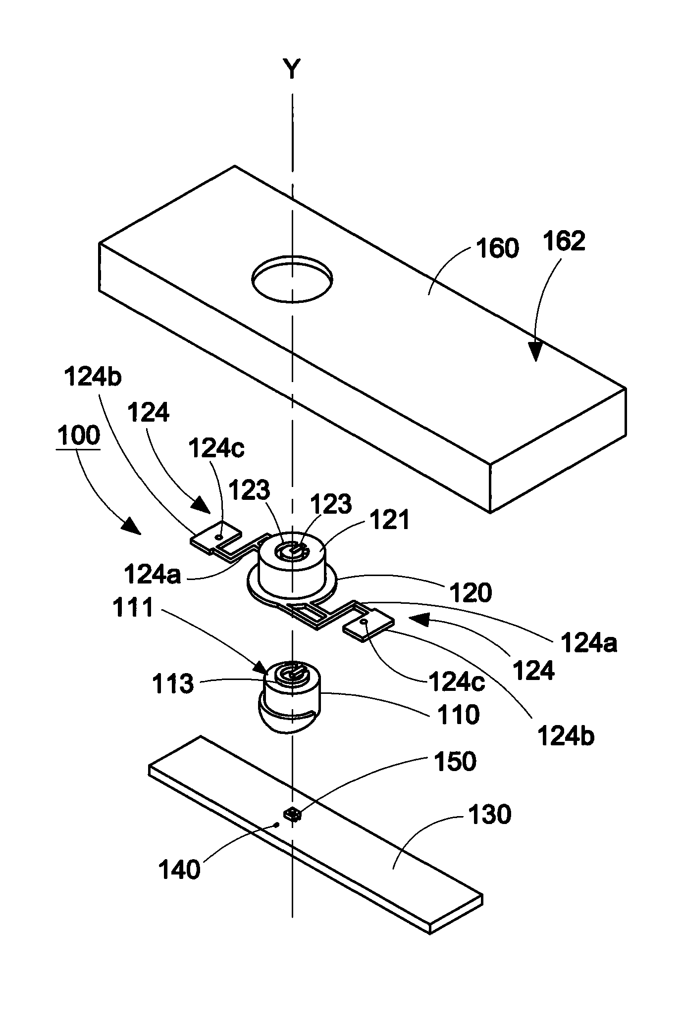
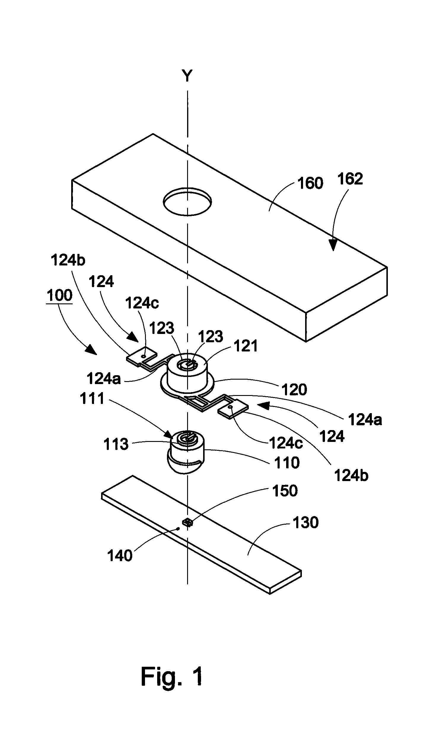
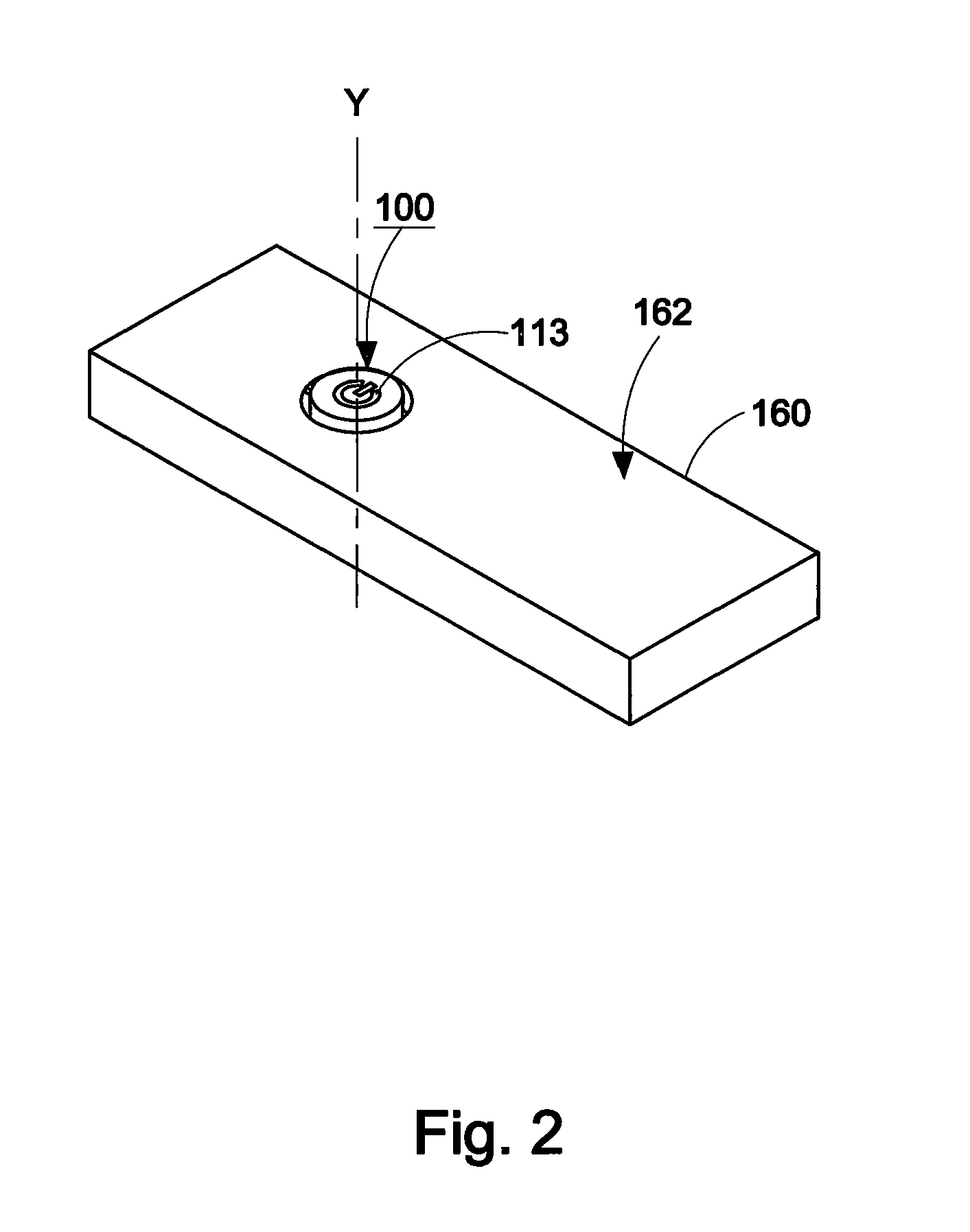
[0042]Referring to FIGS. 1 and 2, an illumination button 100 according to the present invention shown, the illumination button 100 includes a light guide body 110 and a button cap 120. The light guide body 110 is combined with the button cap 120, and light can be received to highlight local pattern features.

[0043]Referring to FIGS. 1 and 3, the light guide body 110 is made of light-pervious material.

[0044]However, the material is not limited to colorless light-pervious material. The material of the light guide body 110 may be a colorless light-pervious material mixed with pigment, such that only visible light of specific colors can pass through the material of the light guide body 110 to show a certain color.

[0045]The light guide body 110 has a top surface 111, a bottom surface 112, a protrusive light exiting structure 113, a protrusive pressing bump 114, and a protrusive light receiving structure 115. The light exiting structure 113 is formed on the top surface 112. The configurati...

second embodiment

[0067]As shown in FIGS. 12 and 13, in a second embodiment, the present invention provides a clamping member 270 applicable to a button structure having a quickly removable button cap. The clamping member 270 includes two positioning hooks 274 and a supporting portion 275. The positioning hooks 274 are disposed on an inner surface of a housing in pair. The supporting portion 275 is disposed on the inner surface of the housing and located between the two positioning hooks 274. Each of the two positioning hooks 274 has an upper block 274a. A slope 274b is formed on an outer surface of the upper block 274a, and is used for guiding an object to slide and push the positioning hook 274 outwardly. The upper blocks 274a of the two positioning hooks 274 are used for pressing against the an upper surface of the latched piece 224b, and the supporting portion 275 is used for contacting a lower surface of the latched piece 224b to support the latched piece 224b, thereby clamping and fixing the la...

third embodiment

[0069]As shown in FIGS. 14 and 15, in a third embodiment, the present invention provides a clamping member 370 applicable to a button structure having a quickly removable button cap. The clamping member 370 includes two positioning hooks 374 and a supporting portion 375. The positioning hooks 374 are disposed on the inner surface of the housing in pair. The supporting portion 375 is disposed on the inner surface of the housing and located between the two positioning hooks 374. The supporting portion 375 is a cylinder having an outer diameter greater than an internal diameter of the positioning hole 324c of the latched piece 324b. The positioning column 380 is monolithically formed on a top surface of the supporting portion 375. Upper blocks 374a of the two positioning hooks 374 press against the upper surface of the latched piece 324b, and a top of the supporting portion 375 contacts the lower surface of the latched piece 324b and supports the latched piece 324b, thereby clamping th...


PUM


Abstract

An illumination button applied to an illumination switch assembly is provided. The illumination button includes a light guide body and a button cap. The light guide body is disposed in the button cap to press a switch element with a pressing bump and to receive light from a light source with a light receiving structure. The light received by the light receiving structure is guided by the light guide body to leave a top surface of the button cap through a light exiting structure. Two connecting members are disposed on an edge the button cap, wherein the two connecting members provided to be clamped by clamping members disposed on an inner surface of a housing, so as to hold the button cap in a button hole of the housing. Therefore, the button cap is able to be installed to the housing quickly with out using a tool.

Description

CROSS-REFERENCES TO RELATED APPLICATIONS[0001]This non-provisional application claims priority under 35 U.S.C. §119(a) on Patent Application No. 98127356 filed in Taiwan, R.O.C. on Aug. 14, 2009, the entire contents of which are hereby incorporated by reference.BACKGROUND OF THE INVENTION[0002]1. Technical Field[0003]The present invention relates to the illumination of buttons, and more particularly to an illumination button, an illumination switch assembly, and a button structure having a quickly removable button cap.[0004]2. Related Art[0005]A button is usually equipped with a button symbol on a top surface of the button cap, such that a user may rapidly recognize the function corresponding to the button. When an electronic device is operated in poor illumination environment, the user is usually unable to recognize the position of the button and the button symbol on the button rapidly. Therefore, the user cannot correctly operate the button. In order to solve the above problems, i...

Claims


Application Information

Patent Timeline
Patent Type & Authority Applications(United States)
IPC IPC(8): H01H9/00H01H13/14
CPCH01H13/023H01H13/14H01H2235/006H01H2221/044H01H2221/08H01H2219/062
Inventor LIN, CHENG-HSUANLIN, YUNG-FENGCHEN, MEI-HUI
Owner WISTRON CORP
Why Eureka
Try Eureka