Planar illumination device and liquid crystal display

a technology of liquid crystal display and illumination device, which is applied in the direction of static indicating device, lighting and heating apparatus, instruments, etc., can solve the problems of difficult to locate light sources, large screen density, and light sources provided on the edge surfaces of light guide plate that cannot be applied to large screen

Inactive Publication Date: 2011-02-17
PANASONIC CORP
View PDF13 Cites 41 Cited by
  • Summary
  • Abstract
  • Description
  • Claims
  • Application Information

AI Technical Summary

Benefits of technology

[0011]Patent Literature 1: JP 1997-034371 A
[0012]Patent Literature 2: JP 2005-249942 A
[0013]Patent Literature 3: US 2008 / 0186273 A1

Problems solved by technology

However, the edge light type in which the light sources are provided on the edge surfaces of the light guide plate cannot be applied to a large screen, which is a problem.
Therefore, the larger the screen, the more the required light flux density increases, which makes it difficult to locate light sources.
Furthermore, the heat generation density also increases, so that heat dissipation is rendered difficult.
Although this problem can be eased if the luminescence efficiency of light sources is improved, there still remains the problem of difficulty in achieving high contrast and power saving to be brought about by the aforementioned local area control in the edge light type.
Therefore, the above-mentioned problems of locating light sources and dissipating heat do not occur in use for a large screen.
That is the reason for the thickness reduction being limited in the display apparatus.
When a number of LEDs are used as in the above case, the cost of light sources and the cost of drive circuits increase, thereby causing an increase in price of the apparatus.

Method used


Image

  • Planar illumination device and liquid crystal display
  • Planar illumination device and liquid crystal display
  • Planar illumination device and liquid crystal display

Examples


embodiment 1

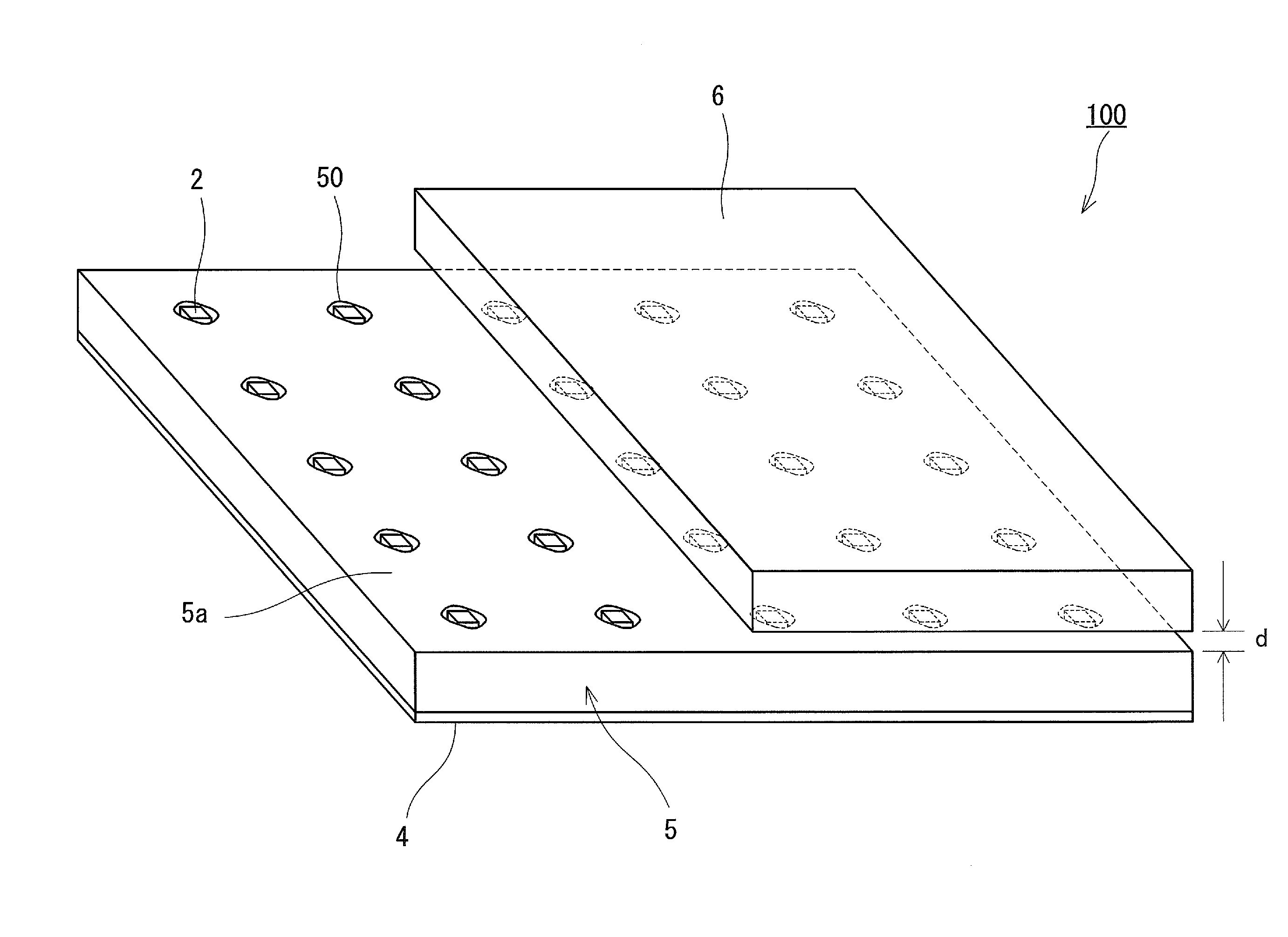
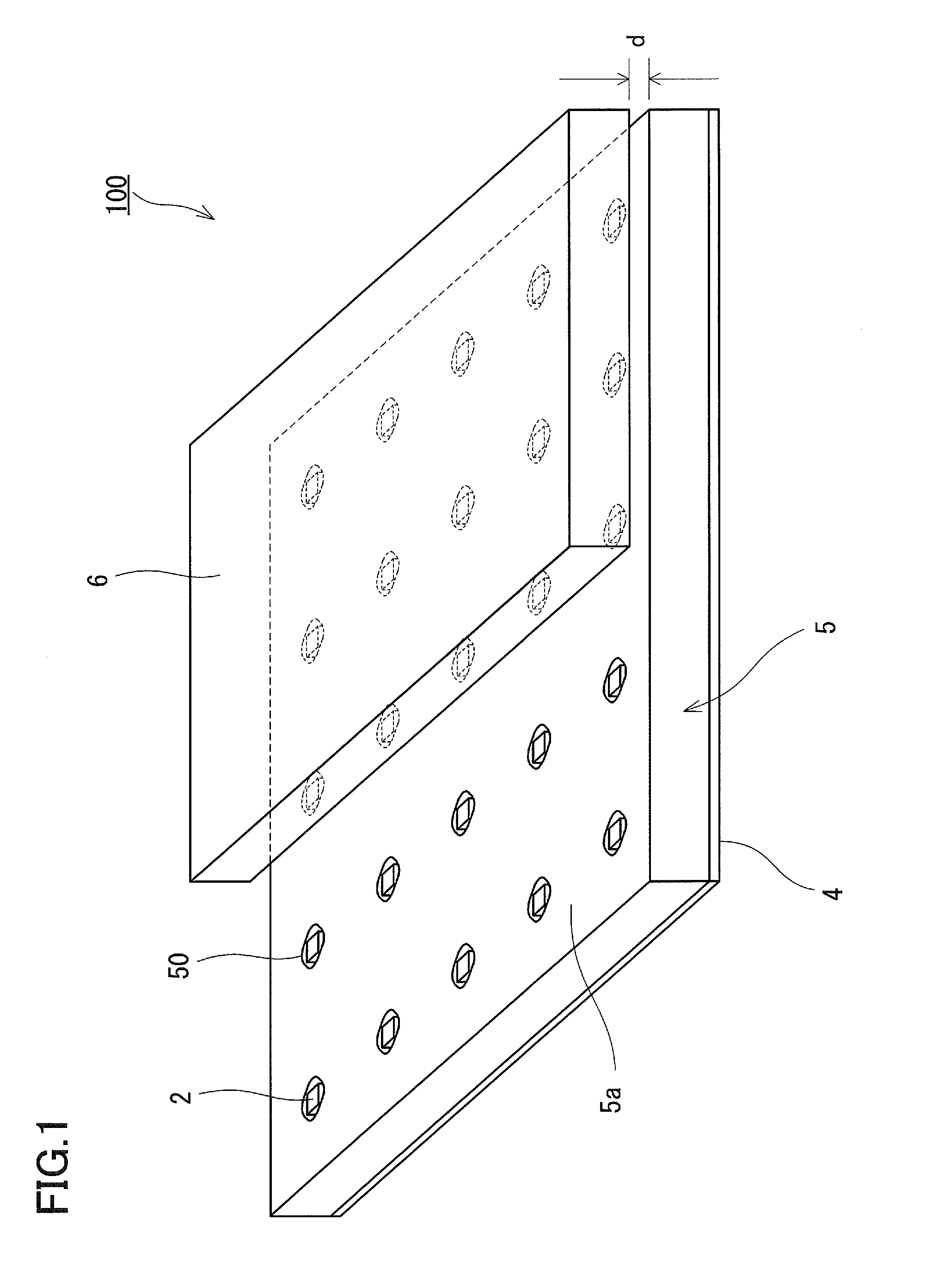
[0035]FIG. 1 is a perspective view showing the schematic configuration of a planar illumination device 100 according to Embodiment 1 of the present invention. FIG. 2 is a partial sectional view showing the schematic configuration of the planar illumination device 100. It should be noted that, in FIG. 1, the illustration of the left side of a diffusion plate 6 is cut off and the illustrations of optical sheets 7 and a mounting substrate 1 that are shown in FIG. 2 are omitted so that the main part can be viewed easily.

[0036]The planar illumination device 100 includes the mounting substrate 1, a plurality of light sources 2 each mounted on a mounting surface 1a of the mounting substrate 1 with a solder bump 3, a reflective sheet 4 that covers the mounting surface 1a of the mounting substrate 1 without interfering with the light sources 2, and a light guide plate 5 between which and the mounting substrate 1 the reflective sheet 4 is interposed. Further, the diffusion plate 6 is provided...

modified embodiment

[0060]In the above-mentioned embodiment, the reflector 24 that serves to prevent light from the light source 2 from directly entering the diffusion plate 6 and thereby serves to allow the light to efficiently enter the light guide plate 5 is provided in close contact with the transparent resin 23. However, the present invention is not limited thereto. For example, as shown in FIG. 8, the reflector 24 may be provided separately from the resin portion 23. That is, the reflector 24 may be attached to the light exit surface 5a of the light guide plate 5 so as to cover each of the accommodating holes 50, and an air layer may be formed between the reflector 24 and the resin portion 23. In this case, highly uniform illumination can be expected by surely preventing light from leaking through the gap between the light source 2 and the incident surface 50a of the light guide plate 5.

[0061]Further, as shown in FIG. 9, the surface of the resin portion 23 on the opposite side of the substrate 21...

embodiment 2

[0068]Next, Embodiment 2 of the present invention is described with reference to FIG. 13. FIG. 13 is a block diagram showing the configuration of a liquid crystal display apparatus 10 according to Embodiment 2 of the present invention.

[0069]The liquid crystal display apparatus 10 is provided with a backlight 100, a liquid crystal panel 200 provided on the light exit side of the backlight 100, an image signal generator 300, a liquid crystal drive circuit 400, and a light source drive circuit 500.

[0070]The backlight 100 in FIG. 13 is the planar illumination device 100 described in Embodiment 1. The light source drive circuit 500 that serves as a controller controls the luminescence intensity of a plurality of the light sources 2 provided on the same plane that are components of the backlight 100, for each specific area.

[0071]The liquid crystal drive circuit 400 controls the liquid crystal panel 200 in response to image signals from the image signal generator 300 and allows images to b...


PUM


Abstract

A planar illumination device (100) is provided with a plurality of light sources (2) provided on a same plane, a light guide plate (5) having a plurality of accommodating holes (50) accommodating the light sources (2) separately, and a diffusion plate (6) provided facing a light exit surface (5a) of the light guide plate (5). Each of the plurality of accommodating holes (50) has a shape corresponding to a shape of each of the plurality of light sources (2) such that a light flux angular density of the light transmitted through the internal surface of the accommodating hole, in an angular direction around the center of the light source (2) accommodated in the accommodating hole (50) as viewed from a direction orthogonal to the plane, increases toward each vertex of a unit section that surrounds the light source (2) in the light guide plate (5).

Description

TECHNICAL FIELD[0001]The present invention relates to a planar illumination device and a liquid crystal display apparatus using the planar illumination device as a backlight.BACKGROUND ART[0002]Thin and lightweight liquid crystal display apparatuses capable of displaying images have spread rapidly due to the development of image enhancement technology and the price reduction resulting from the progress of production technology, and are now widely used as a monitor for personal computers, a TV receiver or the like.[0003]Transmissive liquid crystal display apparatuses are used generally as a liquid crystal display apparatus. Such a transmissive liquid crystal display apparatus is provided with a planar illumination device called a backlight, and forms images by spatially modulating illumination light from the planar illumination device with a liquid crystal panel.[0004]The backlight system mainly is represented by: an edge light type that uses a light guide plate with light sources be...

Claims


Application Information

Patent Timeline
Patent Type & Authority Applications(United States)
IPC IPC(8): G09G5/00F21V8/00G09G3/36
CPCG02B6/0018G02B6/0031G02F1/133603G02B6/0078G02B6/0083G02B6/0055
Inventor YAMAGUCHI, HIROSHI
Owner PANASONIC CORP
Why Eureka
Try Eureka