Medical system comprising a percutaneous probe

a technology of percutaneous interstitial probes and medical systems, which is applied in the field of medical systems comprising percutaneous probes, can solve the problems of inconvenient use, poor interest in percutaneous interstitial probes, and inconsistent inconvenient treatment monitoring, and achieve the effect of preventing interpatient contamination

Active Publication Date: 2011-02-17
ASSISTANCE PUBLIQUE HOPITAUX DE PARIS
View PDF36 Cites 49 Cited by
  • Summary
  • Abstract
  • Description
  • Claims
  • Application Information

AI Technical Summary

Benefits of technology

[0046]disposable technology prev

Problems solved by technology

Percutaneous interstitial probes have initially received poor interest since they require a tissue penetration whereas previous probes don't penetrate the tissue.
Most described ultrasound percutaneous probes are not MRI compatible so that treatment monitoring is somewhat hazardous.
In particular, external probes, although non intrusive, have shown consistent inconvenient: ultrasound attenuation, phase aberration and ultrasound defocalization by tissue structure (bone, tissue interfaces .
. . ), long treatment duration, unknown consequences on crossed normal tissue by the ultrasounds pathway, complexity of the probes with nowadays hundreds of ultrasound transducers, complexity to make the system MRI compatib

Method used


Image

  • Medical system comprising a percutaneous probe
  • Medical system comprising a percutaneous probe
  • Medical system comprising a percutaneous probe

Examples


first embodiment

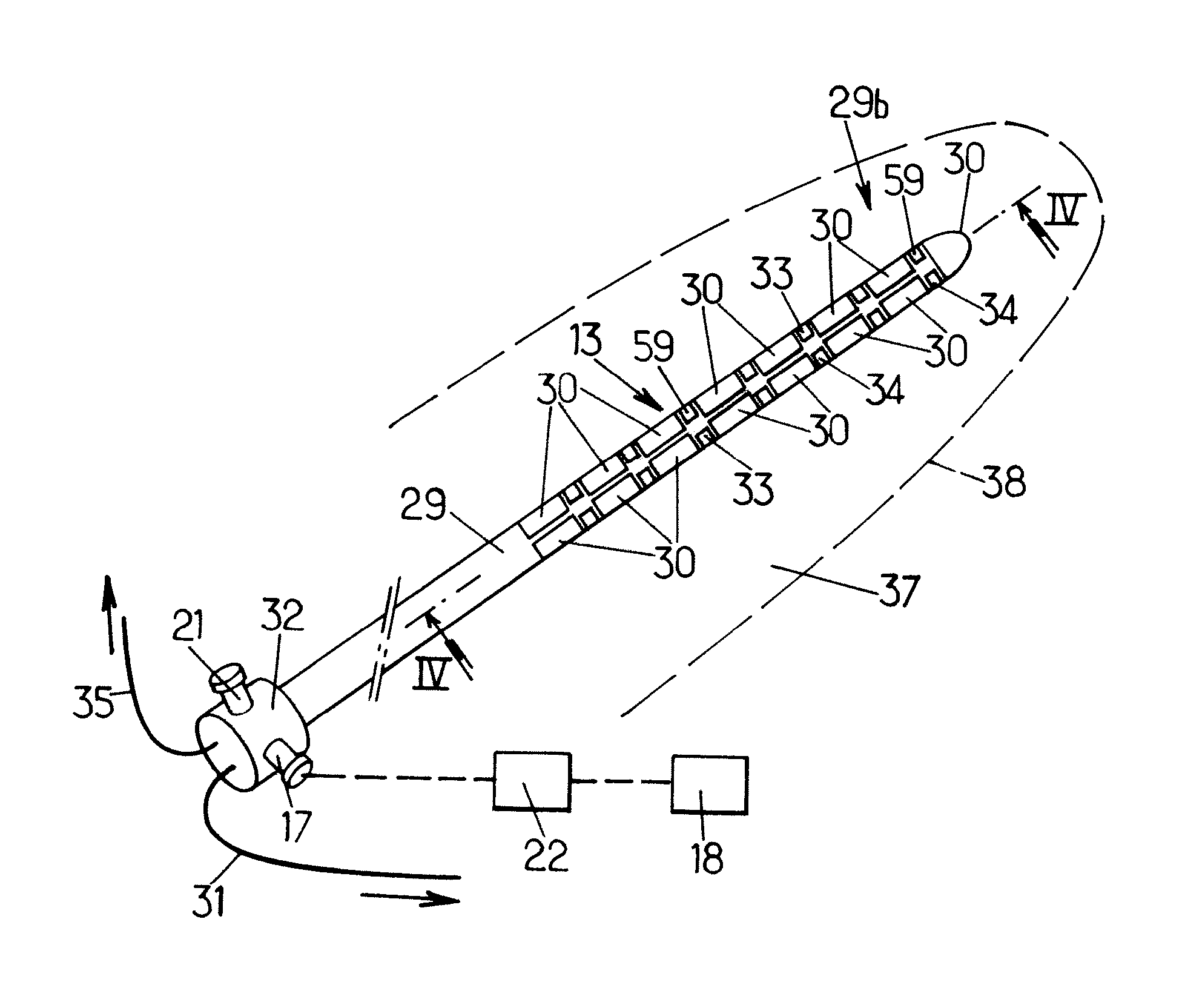
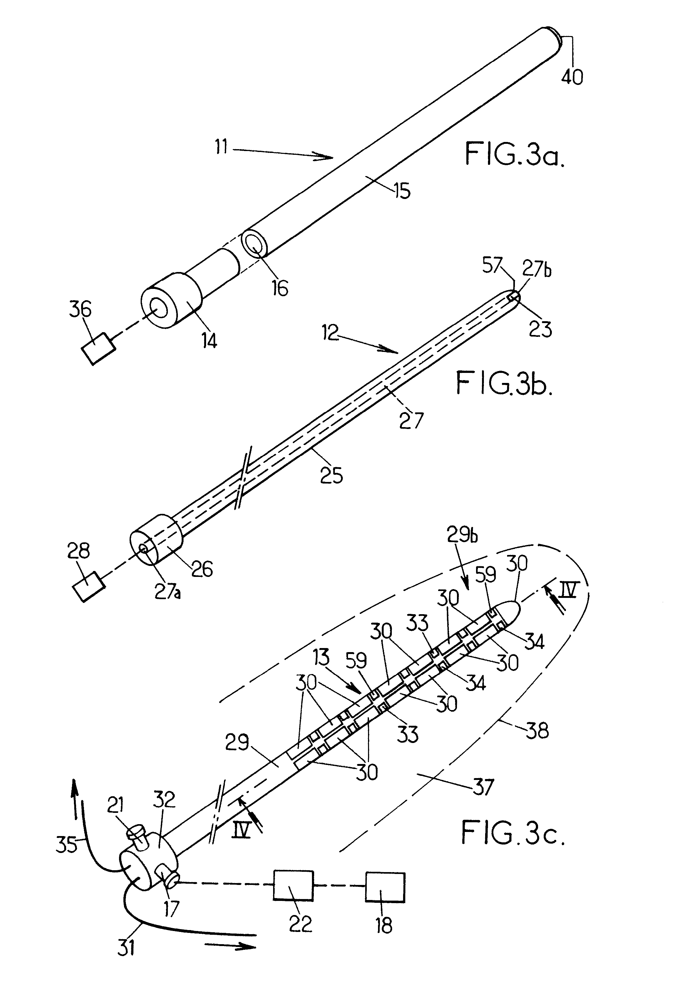
[0068] as shown on FIGS. 3a, 3b and 3c, the probe 6 comprises a plurality of components: an applicator 11 (FIG. 3a), a mandrel 12 (FIG. 3b), and an ultra-sound device 13 (FIG. 3c).

[0069]The applicator 11 comprises a proximally-located back portion 14 and a somehow cylindrical body 15 defining an internal cylindrical cavity 16 which extends throughout the body 15 to a tip in which an end opening 40 is formed.

[0070]The medical system can further comprise a continuous pump 36 to be placed in fluid communication with the cavity 16 of the applicator 11, or removed therefrom. The pump can thus be operated to collect tissue fragments which can later be analyzed, for example by the clinician, to provide tissue information.

[0071]The pump 36 can be operated to extract any material to be extracted from the patient, such as, for example, air bubbles that artifact images, and / or inject into the patient suitable liquids.

[0072]The inner mandrel 12 is made of a rigid material and is shaped so as to...

fourth embodiment

[0094]In this fourth embodiment, the probe still comprises the rigid mandrel 12 of the two previous embodiments.

[0095]A fifth embodiment is partially shown on FIG. 10. This fifth embodiment differs from the third or fourth embodiment in that it has no side openings.

[0096]FIG. 11a partially shows a sixth embodiment of a device 39. When compared to the device of the fifth embodiment, this sixth embodiment differs by a concave arrangement of the transducers, for example in a central portion of the device 39. For example, no sensors are found in this central portion. Thus, instead of being purely cylindrical, the body 15 has, in this embodiment, a thinned central portion. According to another embodiment, as shown on FIG. 11b, the central portion could be convex.

[0097]Such convex or concave shapes could be used for any of the ultra-sound carrying components of the above embodiments.

[0098]It is contemplated that other geometries could be used provided the ultra-sound device is still able ...


PUM


Abstract

The percutaneous probe, made in MRI-compatible materials, comprises: a body percutaneously inserted into the tissue of a patient's body organ (8) having a region (10) to be analyzed, treated and monitored during a single medical procedure; at least one information collection sensing device (30,33,34); treatment application transducers (30) 360° disposed to emit focused or defocused therapeutic ultra-sound waves. The computerized system comprises a parametrizable command device (50) adapted to simulate then command a generation of the therapeutic ultra-sound waves, and to monitor the treatment by thermal MRI images.

Description

FIELD OF THE INVENTION[0001]The instant invention relates to medical systems comprising percutaneous probes, and to uses of such medical systems.BACKGROUND OF THE INVENTION[0002]Low intensity ultrasounds are widely used in medicine for diagnostic procedures, i.e. echography. For 10 years, high intensity ultra-sounds have shown to be an efficient means to induce tissue necrosis by hyperthermia for treatment procedures. Various therapeutic probes have been designed for minimally invasive therapeutic procedures and can be classified in two groups: external probes and internal probes.[0003]External probes are designed to mimic the shape of the surface of the patient's body. Ultrasound transmitters are displayed in a concentric fashion to optimise the ultrasound waves focalization.[0004]Internal / interstitial probes are inserted inside the body of the patient. There are three main categories: endo-cavity, endovascular or percutaneous probes.[0005]A. Endocavity Probes[0006]Endocavity probe...

Claims


Application Information

Patent Timeline
IPC IPC(8): A61B8/00A61N7/00A61B5/055
CPCA61B5/0068A61N2007/025A61B5/01A61B5/0402A61B5/0476A61B5/055A61B5/6848A61B8/0833A61B8/12A61B2017/00084A61B2017/00911A61B2019/5236A61B2019/528A61N7/02A61N2007/0073A61B5/0084A61B2090/3784A61B2090/374A61B5/318A61B5/369
Inventor CARPENTIER, ALEXANDREITZCOVITZ, JULIAN
Owner ASSISTANCE PUBLIQUE HOPITAUX DE PARIS
Why Eureka
Try Eureka