
In situ offset compensation for pressure sensors

a pressure sensor and offset compensation technology, applied in the field of pressure sensor output reading verification, can solve the problems of increasing the risk of false pressure reading, dramatic and unhealthy increases in intracranial pressure, and the brain cannot adapt to any increase in fluid volume, so as to minimize handling errors and accurate correction of sensors

Active Publication Date: 2011-02-17
INTEGRA LIFESCI SWITZERLAND SARL
View PDF13 Cites 31 Cited by
  • Summary
  • Abstract
  • Description
  • Claims
  • Application Information

AI Technical Summary

Benefits of technology

[0016]An object of the present invention is to provide accurate corrections of sensors while minimizing handling errors in the operating room and during use of the sensors in situ.
[0018]Yet another object of the invention is reduce the time needed to prepare pressure sensors before implantation.

Problems solved by technology

As soon as the brain's auto-regulation or compensatory mechanisms fail, or if too great a trauma to the head occurs, blood and cerebrospinal fluid cannot be displaced, and the brain can no longer adapt to any increase in fluid volume.
As more fluid volume is added, a threshold is reached beyond which small increases in volume lead to dramatic and unhealthy increases in intracranial pressure.
Other types of pressure sensors are zeroed during manufacture and the null point is transferred to a patient monitor which may introduce an error and increase the risk of a false pressure reading.
Capacitive sensors suffer from drift due to electronic interference with fluids due to stray capacitive effects or changing electrical potentials of surrounding conductive bodily fluids.

Method used


Image

  • In situ offset compensation for pressure sensors
  • In situ offset compensation for pressure sensors
  • In situ offset compensation for pressure sensors

Examples


Embodiment Construction

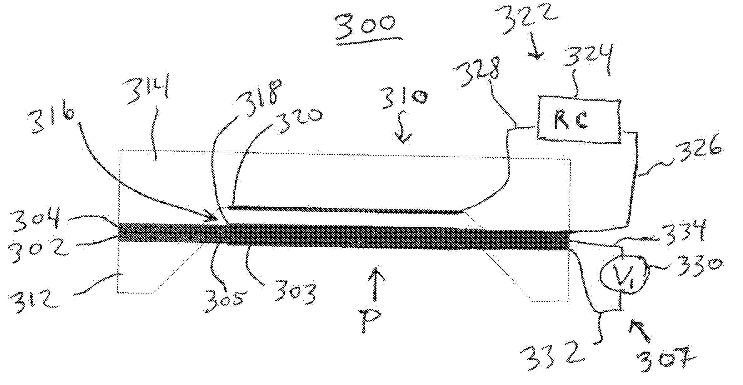
[0036]Pressure sensors according to the present invention have a substrate and a first, deformable sensor membrane, partially supported by the substrate, which generates a first sensor reading when deformed by pressure. A second membrane is contiguous to the first membrane. When the second, contiguous membrane is energized, it deforms the first membrane to alter the first sensor reading.

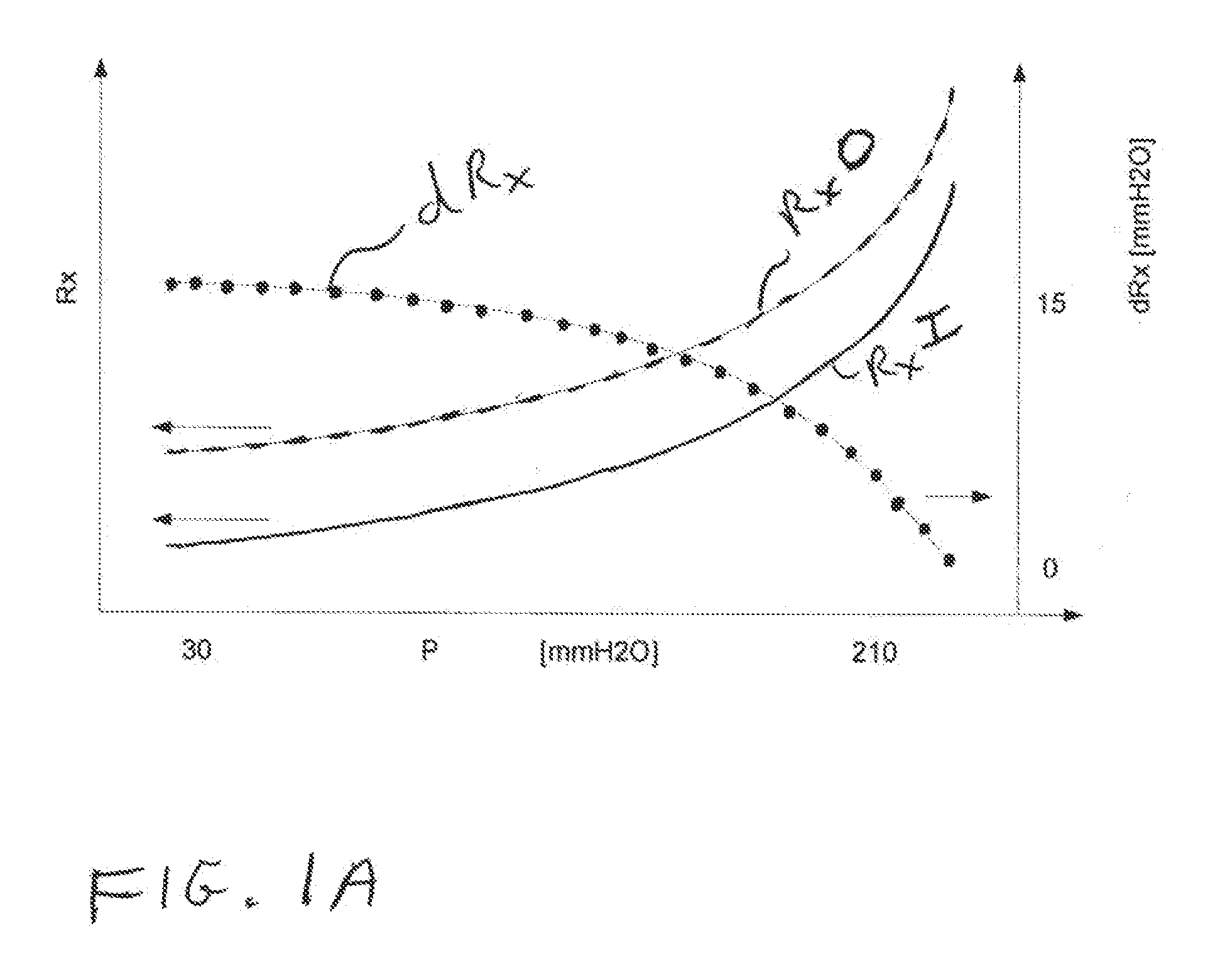
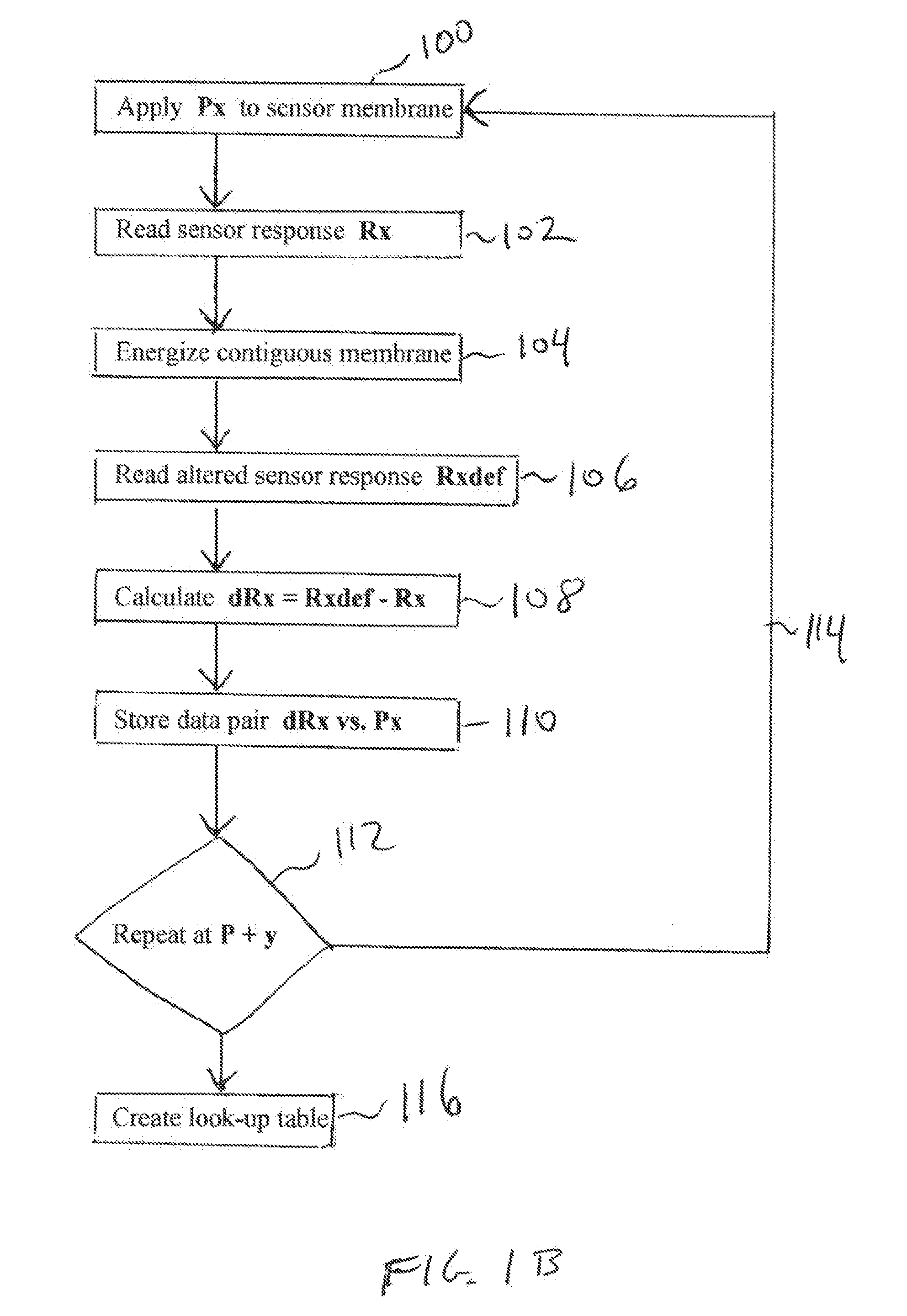
[0037]A difference in the response of the pressure sensor with the second, contiguous membrane in an inactive, unenergized state and then in an active, energized state is first utilized under controlled pressure conditions, such as during production of the pressure sensor, to match actual pressures to a plurality of delta response values for that sensor. FIG. 1A depicts an example of an initial sensor response curve RxI, with pressures in mmH2O on the x-axis and obtained sensor readings Rx on the left-hand y-axis, while the second membrane is inactive. This corresponds to steps 100 and 102, FIG. 1B, ...


PUM

PropertyMeasurementUnit
pressureaaaaaaaaaa
capacitanceaaaaaaaaaa
piezoelectricaaaaaaaaaa

Abstract

A pressure sensor having a substrate and a first, deformable membrane, partially supported by the substrate, which generates a first sensor reading when deformed by pressure. A second membrane is contiguous to the first membrane. When the second membrane is energized, it deforms the first membrane to alter the first sensor reading.

Description

CROSS-REFERENCE TO RELATED APPLICATION[0001]This application claims priority to U.S. Provisional Application No. 61 / 233,395 by Burger et al. filed Aug. 12, 2009 entitled “Ultrathin Multilayers for a Hermetic Packaging”.BACKGROUND OF THE INVENTION[0002]1. Field of the Invention[0003]The invention relates to verification of output readings for pressure sensors and more particularly to pressure sensing compound membranes which are deformable both by ambient pressure and electrical activation.[0004]2. Description of the Related Art[0005]Human brain tissue includes gray and white matter suspended in cerebrospinal fluid within the cranium and nourished by blood delivered through cerebral arteries. The gray matter has closely spaced cell bodies of neurons, such as in the cerebral cortex, and the underlying white matter contains densely packed axons that transmit signals to other neurons. Brain tissue has different densities and comprises approximately eighty percent of the intracranial con...

Claims


Application Information

Patent Timeline
Patent Type & Authority Applications(United States)
IPC IPC(8): A61B5/03G01L9/12G01L9/06
CPCA61B5/0031A61B5/031G01L27/002A61B2560/0223G01L19/02A61B5/6846A61B5/032A61B2562/0247
Inventor BURGER, JUERGENBORK, TORALF
Owner INTEGRA LIFESCI SWITZERLAND SARL
Learn More