[0020]The guide wire is typically clamped, at a location proximal to a proximal end of the interventional catheter, prior to advancing the interventional catheter. Activation of high speed rotational catheters and / or operating heads breaks the
static friction between the guide wire and the rotational drive
system, allowing the rotational catheter, drive
system and operating head to move readily over the static (clamped) guide wire as the operating head is advanced and / or retracted through the
target site. Guide wire management systems and methods of the present invention provide a guide wire
buffer zone positioned between the location where the guide wire exits the interventional catheter (or the controller) and the guide wire clamp that allows variable lengths of exposed guide wire to accumulate in a generally unsupported and unconstrained condition as the interventional catheter is advanced distally over the guide wire during an intervention.
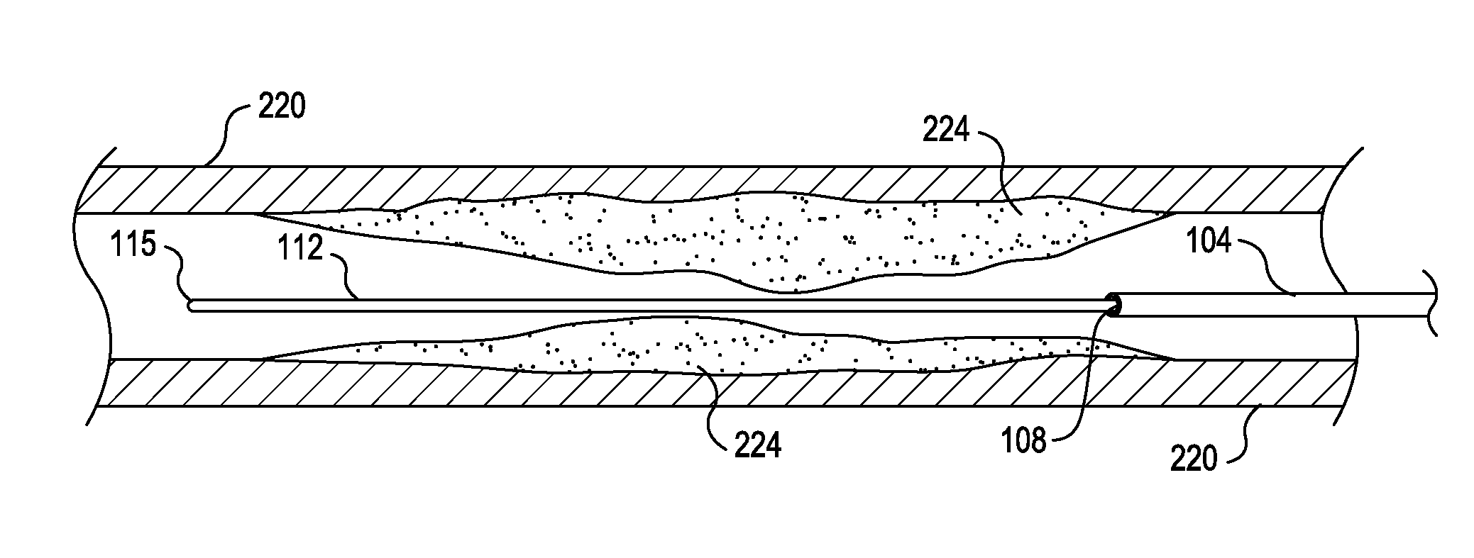
[0022]When the interventional catheter is retracted proximally over the guide wire following an advance, the process is reversed. The relative axial movement of the interventional catheter with respect to the guide wire during retraction exposes more guide wire distally in proximity to the intervention site and diminishes the excess length of guide wire accumulated in the guide wire buffer zone. As the length of guide wire exposed in the buffer zone diminishes, curves having progressively smaller profiles are formed. In this way, the interventional catheter and operating head may be advanced and retracted for long distances over the guide wire without requiring guide wire clamp adjustments and without compromising or damaging the guide wire.
[0023]Guide wire management systems of the present invention thus provide that the clamping portion of the guide wire brake is positioned (or positionable) at a distance from the location where the guide wire exits the controller (or the interventional catheter), forming a guide wire buffer zone in which the guide wire is substantially unrestrained and generally unsupported. Variable lengths of guide wire may be conveniently accommodated in the guide wire buffer zone without changing the position of the controller, the interventional catheter, or the guide wire clamp, allowing the distal end of the operating catheter, and an (optional) operating head, to be advanced and retracted over the guide wire without repositioning the guide wire or adjusting the guide wire clamp. Associating and / or functionally integrating a guide wire brake and guide wire buffer zone with an interventional catheter
assembly in the arrangements disclosed herein provides many advantages in terms of operator convenience, improved
accuracy and precision in guide wire positioning and / or fixation, and better control of desired catheter and operating head motions and operation during an intervention. These advantages facilitate quicker interventions and require fewer operator manipulations, thereby improving the safety and
efficacy of interventional procedures in general.
[0024]In general, an integrated guide wire buffer zone of the present invention is designed and configured to accommodate the changes in the relative position of the distal end of the catheter (and / or operating head) with respect to a fixed guide wire, with the guide wire length buffer zone operating to provide a space for effectively allowing excess guide wire length to accumulate as the operating head is advanced, and allowing the excess guide wire length to be taken up as the operating head is retracted. The guide wire buffer zone of the present invention is designed, incorporated and functionally integrated with the catheter
assembly, the controller or housing, and the guide wire brake, providing a guide wire
management system that effectively and conveniently accommodates changes in exposed guide wire length at the proximal end of the catheter and controller as the catheter and operating head are advanced and retracted during an interventional procedure.
[0026]In some embodiments, the position of the guide wire clamp is adjustable, allowing an operator to adjust the position of the guide wire clamp closer to or farther from the guide wire exit port. The space between the guide wire exit port and the guide wire clamp location defines the integrated guide wire buffer zone positioned between the controller (and / or a proximal end of the interventional catheter assembly) and the guide wire clamp. When the guide wire clamp is positioned relatively closer to the guide wire exit port, a relatively small guide wire buffer zone is provided, allowing axial translation of the interventional catheter and operating head (e.g. advancement and retraction) over a relatively
short distance without requiring repositioning of the guide wire and reclamping of the guide wire brake. When the guide wire clamp is positioned relatively further away from the guide wire exit port, a relatively large guide wire buffer zone is provided, allowing axial translation of the interventional catheter and operating head (e.g. advancement and retraction) over a relatively long distance without requiring repositioning of the guide wire and reclamping of the guide wire brake. The operator may position an adjustable guide wire clamp prior to and / or during an interventional procedure to provide a relatively small or large guide wire buffer zone, depending on the size and characteristics of the interventional site, the type of intervention, the anticipated travel of interventional catheter and operating head advancements and retractions, and the like.
[0027]In one embodiment providing an adjustable guide wire clamp, the guide wire clamp may be located, for example, at one end of a guide wire clamp housing, while an opposite end of the guide wire clamp housing is pivotably mounted to a controller housing. Providing a pivoting mounting for the guide wire clamp housing permits the guide wire clamp to be spaced a variable and selectable distance from the guide wire exit port, thus changing the dimensions of the guide wire buffer zone. This feature allows the configuration of the guide wire buffer zone to be adjusted and / or optimized by an operator prior to and / or during an intervention based on the anticipated range of relative axial motion of the catheter and operating head and the length of guide wire exposed proximally during operation of the interventional catheter. The position of the guide wire brake and the dimensions of the guide wire buffer zone may also be changed during an intervention to accommodate unanticipated conditions without slowing the procedure, reclamping the guide wire, or repositioning any other components of the interventional catheter assembly.

