
Diffuser for LED light sources

a technology of led light source and diffuser, which is applied in the direction of instruments, lighting and heating apparatus, semiconductor devices for light sources, etc., can solve the problems of reducing luminous efficiency, reducing light loss, and reducing light loss, so as to reduce heat loss and reduce heat loss. , the effect of large surface area

Inactive Publication Date: 2011-02-24
SWITCH BULB CO INC
View PDF108 Cites 15 Cited by
  • Summary
  • Abstract
  • Description
  • Claims
  • Application Information

AI Technical Summary

Benefits of technology

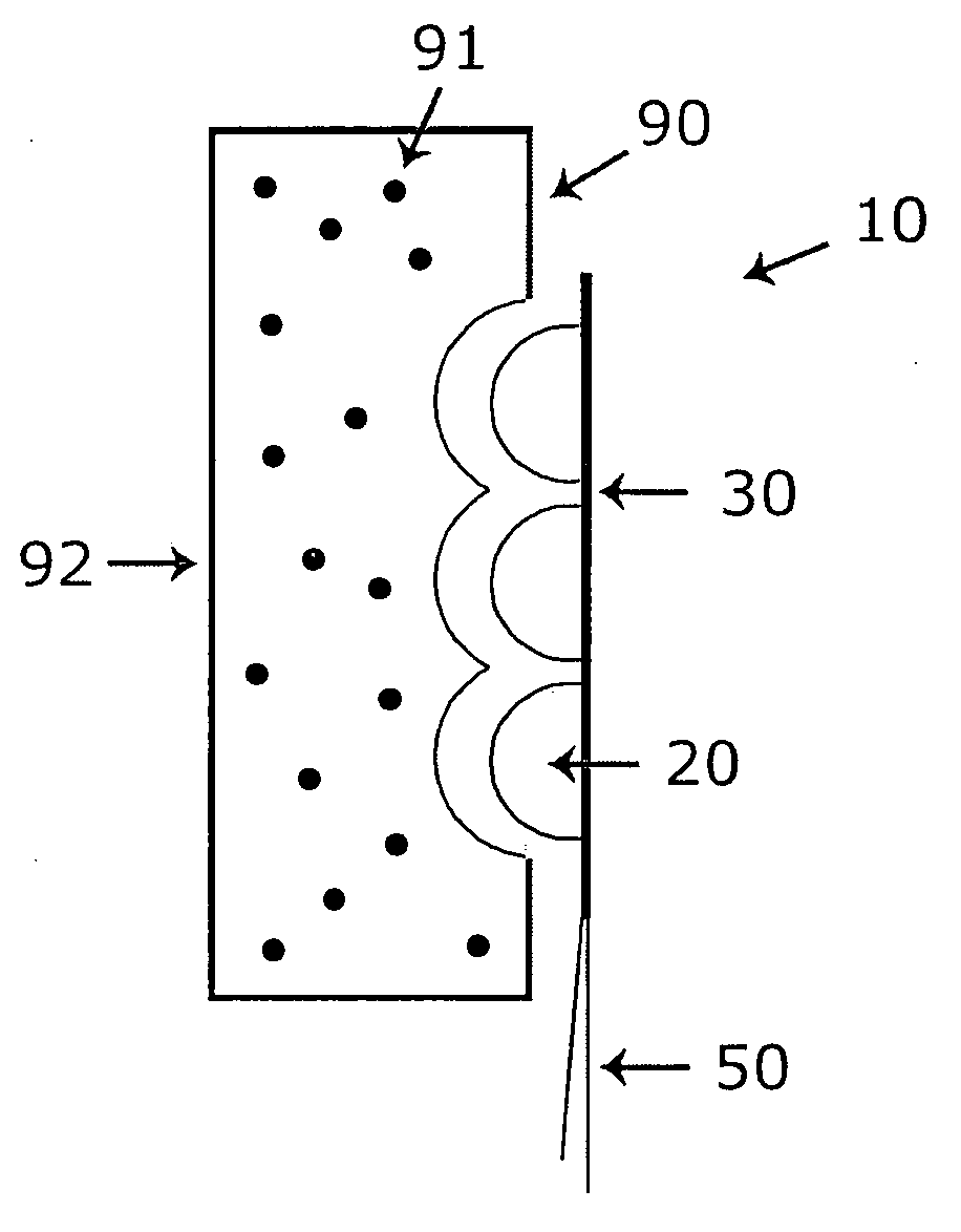
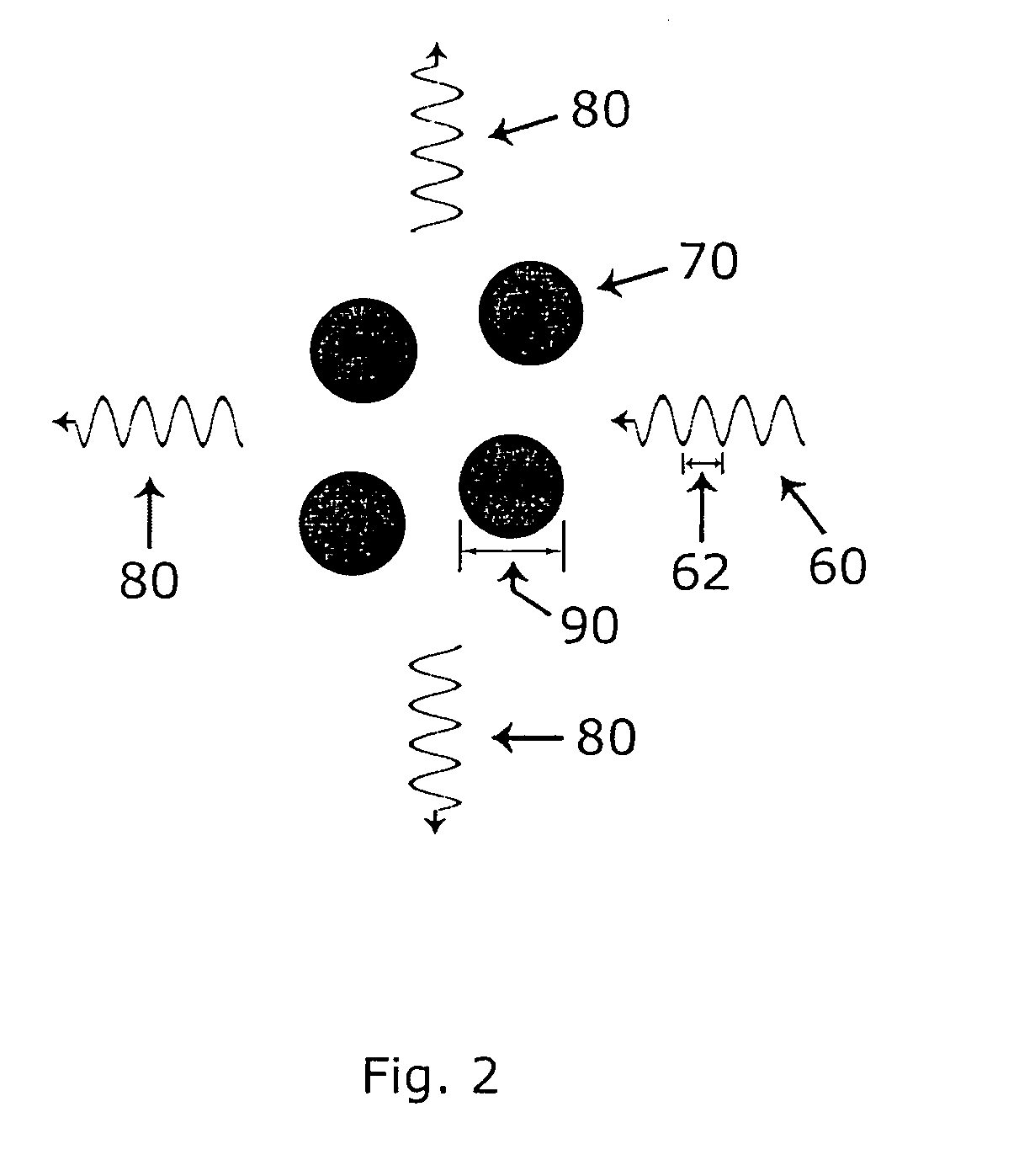
"The invention is a diffuser for LEDs that solves the problem of uneven lighting and heat dissipation. It is attached to an LED light source and uniformly distributes light over the surface with minimal light loss. The diffuser includes a sealed panel made of plastic and a filler material that contains or forms a system of Mie scatterers. The filler material efficiently removes heat from the LEDs and conveys it to a suitable surface for removal. The sealed panel has a rectangular cross-section and can be built into the LED light source assembly or attached using various methods. The fluid, gel, or plastic can be distributed in the sealed panel with a non-uniform spatial distribution to create more intense light in one direction."

Problems solved by technology

However, LEDs have a number of drawbacks that have prevented them, so far, from being widely adopted as traditional lighting sources.
Using multiple LEDs does not fully alleviate this problem, as there are then interference patterns in the light.
Neither of these methods accomplishes uniform light distribution for an LED light source, and may lower luminous efficiency.
Methods of accomplishing approximate angular uniformity may also involve partially absorptive processes, further lowering luminous efficacy.
Another drawback with LEDs is that although LEDs require substantially less power for a given light output than do incandescent bulbs, it still takes many watts to generate adequate light for illumination.
An LED, being a semiconductor, is nearly a point source of heat, and cannot be allowed to get hotter than a range of approximately 85-150° C. The LED thus has a substantial heat problem.
However, this solution is undesirable, because the heat sink may make it difficult for the light source to fit in to the desired form factor.

Method used


Image

  • Diffuser for LED light sources
  • Diffuser for LED light sources
  • Diffuser for LED light sources

Examples


Embodiment Construction

[0016]Reference will now be made in detail to the present preferred embodiments of the invention, examples of which are illustrated in the accompanying drawings. Wherever possible, the same reference numbers are used in the drawings and the description to refer to the same or like parts.

[0017]According to the design characteristics, a detailed description of the current practice and preferred embodiments is given below.

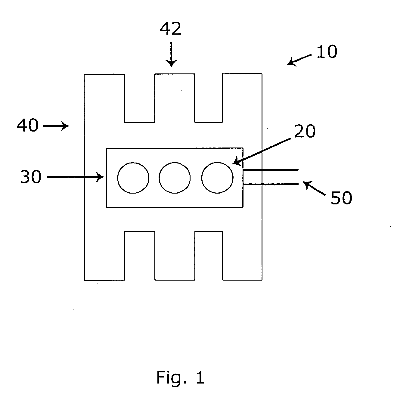
[0018]FIG. 1 is a view of a present state-of-the-art LED light source 10 showing the reason for its directionality of light output and the construction used for removing heat. As shown in FIG. 1, the LEDs 20 are mounted on a circuit board 30. Since said LEDs are point sources of light, the light emitted from the said LED light source appears concentrated in beams. Said circuit board provides electrical interconnects for the LEDs 20, and may also provide electrical isolation. Wires 50 come from the circuit board to power the LEDs from a power source (not shown). The ci...


PUM


Abstract

An LED light source, which includes at least one LED, a panel between the LED and the light emission surface of the light source, and a filler material inside the panel containing a material to diffuse the light from the at least one LED by Mie scattering.

Description

FIELD OF THE INVENTION[0001]The present invention relates to providing uniformly dispersed light from a light emitting diode (LED) source and to the efficient removal of the heat generated by the LEDs, and more particularly, to the uniform dispersion of the light generated by LEDs in a light source without substantial light loss, in order to provide a uniform illumination surface, and to permit the LEDs to be run at higher power.BACKGROUND OF THE INVENTION[0002]An LED consists of a semiconductor junction, which emits light due to a current flowing through the junction. A white LED is typically made by using a blue or ultraviolet LED die, and adding a plastic coat to it, the coat containing a phosphor. The phosphor is used to convert the blue or ultraviolet light emitted by the LED die to a spectrum of light that more or less closely resembles white light or blackbody radiation.[0003]At first sight, it would seem that white LEDs should make an excellent replacement for the traditiona...

Claims


Application Information

Patent Timeline
Patent Type & Authority Applications(United States)
IPC IPC(8): H01L33/50
CPCF21V3/00F21V5/00F21V17/04F21V17/06F21V29/004F21V29/763G02B5/0242G02B5/0278H01L33/58F21V29/225F21Y2101/02F21Y2115/10F21V29/74
Inventor LENK, CAROL
Owner SWITCH BULB CO INC
Learn More