
Monocoque structure of an electrically powered motorized vehicle

a motorized vehicle and monocoque technology, applied in the field of automobiles, can solve the problems of less than optimal mass fraction of electric motor driven cycle, limited range, power efficiency and other performance characteristics, and heavy weight of electrically powered motorized vehicle, and achieve the effects of high strength, light weight and optimal performan

Inactive Publication Date: 2011-02-24
ANANTHAKRISHNA ANIL
View PDF15 Cites 9 Cited by
  • Summary
  • Abstract
  • Description
  • Claims
  • Application Information

AI Technical Summary

Benefits of technology

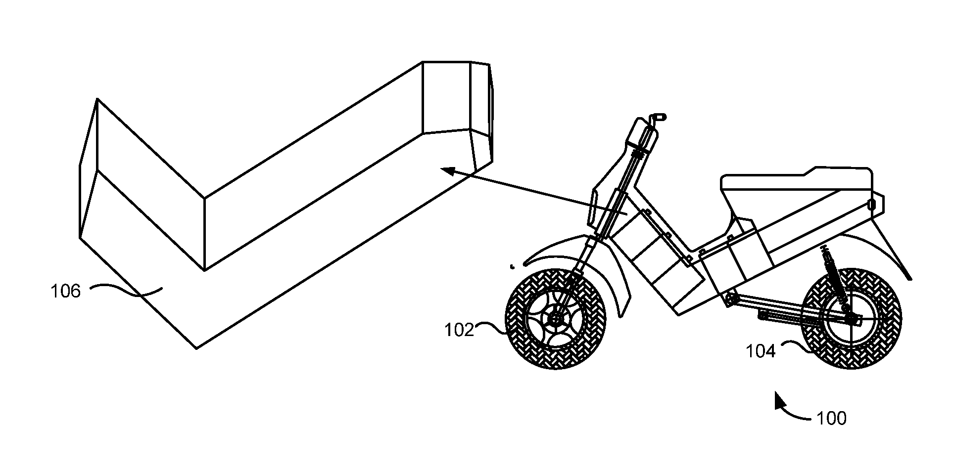
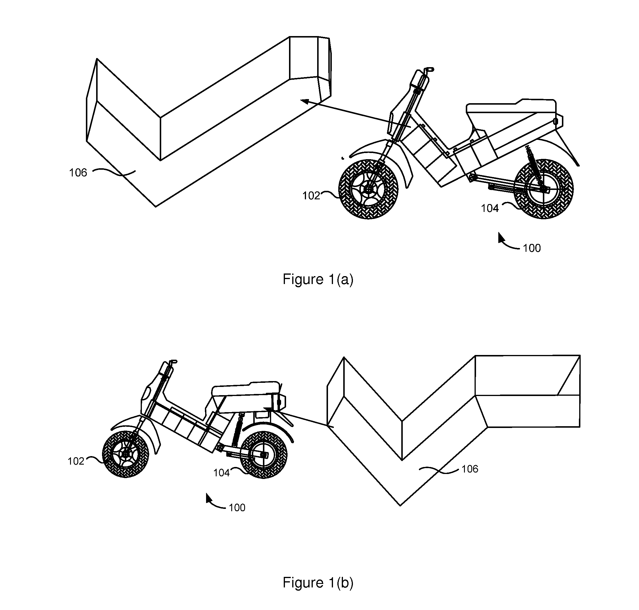
[0007]The primary aspect of the present invention is to provide a unique monocoque structure of an electrically powered motorized vehicle to maximize energy efficiency and automobilist's safety.
[0010]In another aspect, the monocoque frame of the electrically powered motorized vehicle includes one or more compartments to house the internal components of the vehicle. Further, the internal components of the vehicle can be strategically positioned for optimal performance.
[0011]In yet another aspect, the monocoque frame of the electrically motorized vehicle is built with combinations of die-cast, extrusions of high strength plastic and light metal alloys to provide light weight and sufficient rigidity.

Problems solved by technology

However, there exists certain limitation in the range, power, efficiency and other performance characteristics due to the weight of the heavy batteries in the electrically powered motorized vehicles.
Generally, the electrically powered motorized vehicles are heavier compared to the internal combustion engine powered vehicles due to the additional weight of the batteries in the electrically motorized vehicle.
This construction often results in a mass fraction for the electric motor driven cycle that is less than optimal.

Method used


Image

  • Monocoque structure of an electrically powered motorized vehicle
  • Monocoque structure of an electrically powered motorized vehicle
  • Monocoque structure of an electrically powered motorized vehicle

Examples


Embodiment Construction

[0017]The preferred embodiments of the present invention will now be explained with reference to the accompanying drawings. It should be understood however that the disclosed embodiments are merely exemplary of the invention, which may be embodied in various forms. The following description and figures are not to be construed as limiting the invention and numerous specific details are described to provide a thorough understanding of the present invention, as the basis for the claims and as a basis for teaching one skilled in the art about making and / or using the invention. However in certain instances, well-known or conventional details are not described in order not to unnecessarily obscure the present invention in detail.

[0018]The present invention describes an extruded unique monocoque structure of an electrically powered motorized vehicle for minimizing production time, maximizing mechanical stability, maximizing heat dissipation, protection against corrosion and adaptability to...


PUM


Abstract

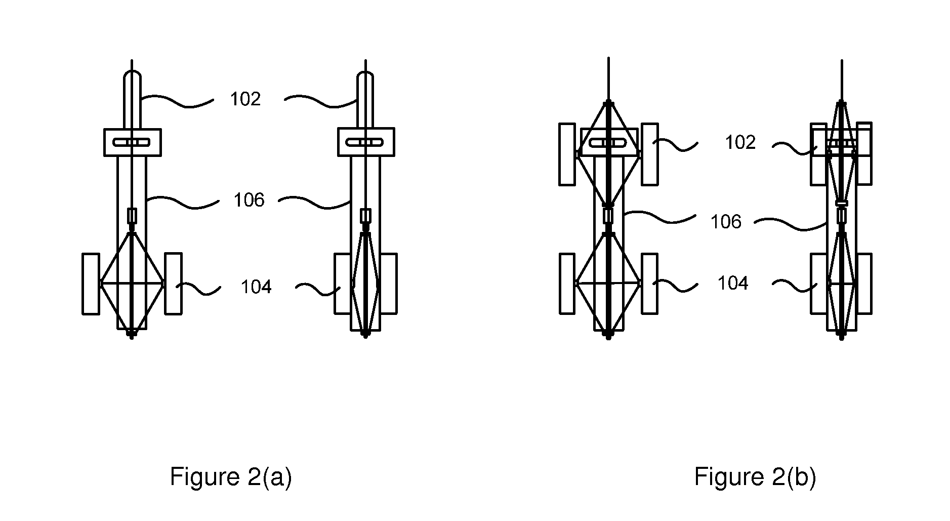
The present invention describes a unique monocoque structure of an electrically powered motorized vehicle. In one embodiment, the structure includes at least two front wheels, wherein the pitch of the front wheels can be extended; at least two rear wheels, wherein the pitch of the rear wheels can be extended; and a monocoque frame suspended between the front wheels and the rear wheels. Further, a control switch is mounted on the monocoque fame to convert two wheeled vehicle to three or four wheeled vehicle and vice versa. Furthermore, the monocoque frame is built with combinations of die-cast, extrusions of high strength plastic and light metal alloys to provide light weight and sufficient rigidity.

Description

RELATED APPLICATIONS[0001]Benefit is claimed under 35 U.S.C. 119(e) to U.S. Provisional Application Ser. No. 61 / 151,829, entitled “MONOCOQUE STRUCTURE OF AN ELECTRICALLY POWERED MOTORIZED VEHICLE” by Anil Ananthakrishna, filed Feb. 11, 2009, which is herein incorporated in its entirety by reference for all purposes.FIELD OF THE INVENTION[0002]The present invention generally relates to the field of automobiles. Particularly, the present invention relates to a structure of an electrically powered motorized vehicle and more particularly, it relates to a unique monocoque structure of an electrically powered motorized vehicle to maximize energy efficiency and automobilist's safety.BACKGROUND OF THE INVENTION[0003]Over the last 150 years, bicycles have been one of the most efficient means of transportation and over a period of time these included an efficient gear system to minimize physical effort while riding. Of late, conventional bicycles have been replaced by electrically powered mot...

Claims


Application Information

Patent Timeline
IPC IPC(8): B62K19/00
CPCB62K11/06B62K2202/00B62K13/06B62K11/10B62K2204/00
Inventor ANANTHAKRISHNA, ANIL
Owner ANANTHAKRISHNA ANIL
Learn More