Electric rotating machine drivable with a single three-phase inverter
a three-phase inverter, electric rotating machine technology, applied in synchronous machines, windings, dynamo-electric components, etc., can solve the problems of etc., to reduce the total magnetic noise and torque ripple and widen the angular range
- Summary
- Abstract
- Description
- Claims
- Application Information
AI Technical Summary
Benefits of technology
Problems solved by technology
Method used
Image
Examples
first embodiment
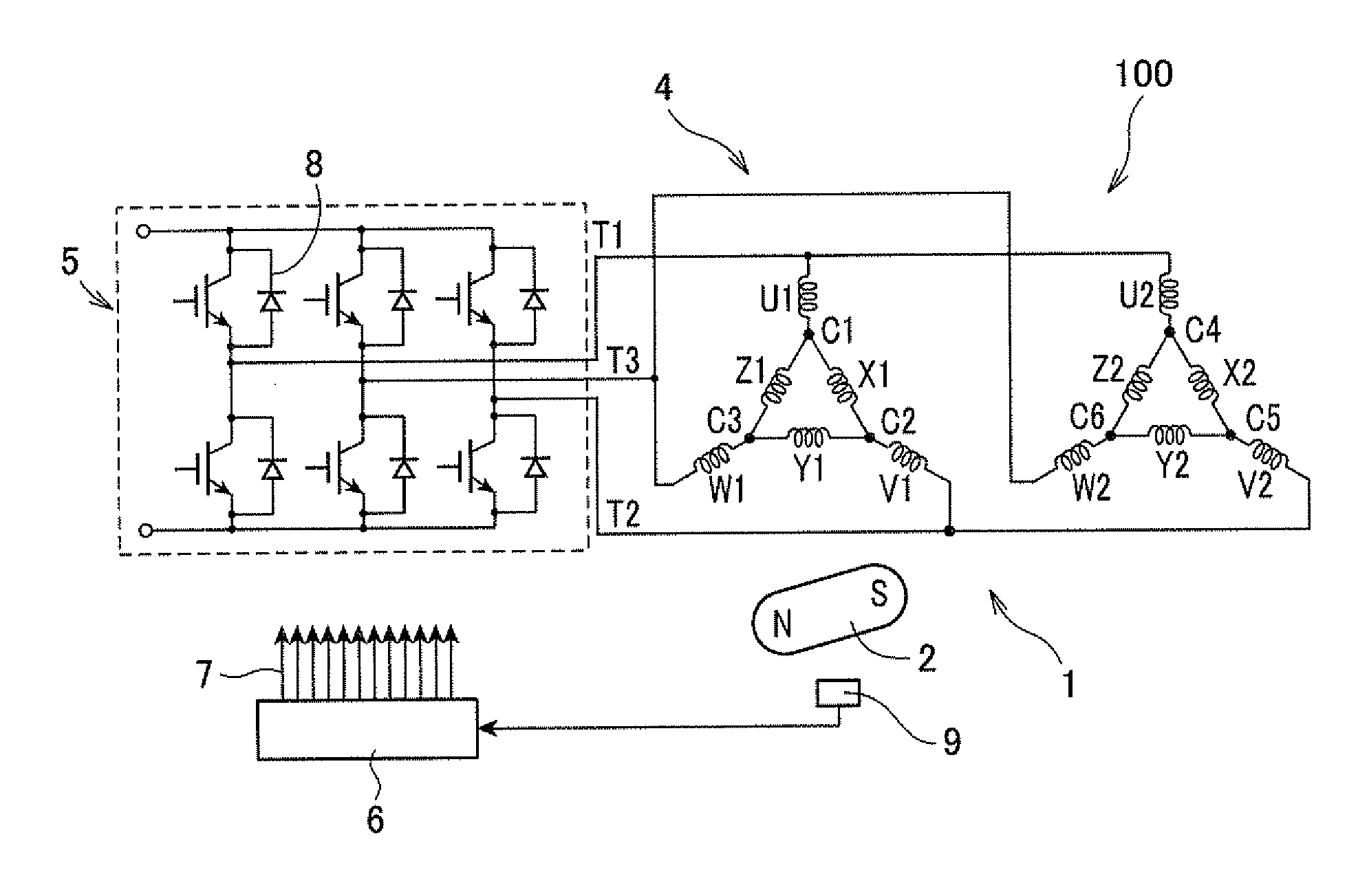
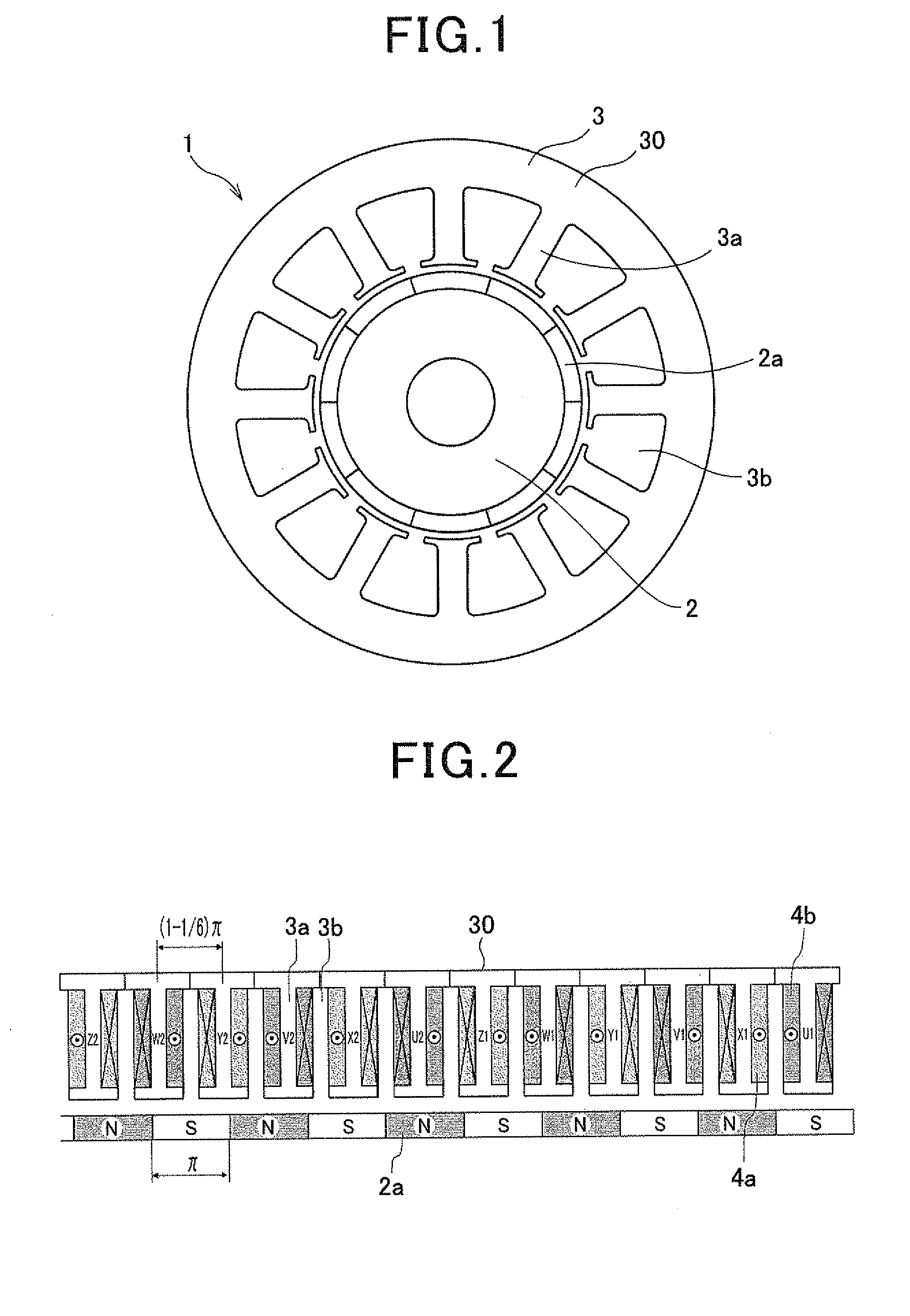
[0037]FIG. 1 shows the overall configuration of an electric rotating machine 1 according to the first embodiment of the invention. As shown in the figure, the electric rotating machine 1 includes a rotor 2 and a stator 3.
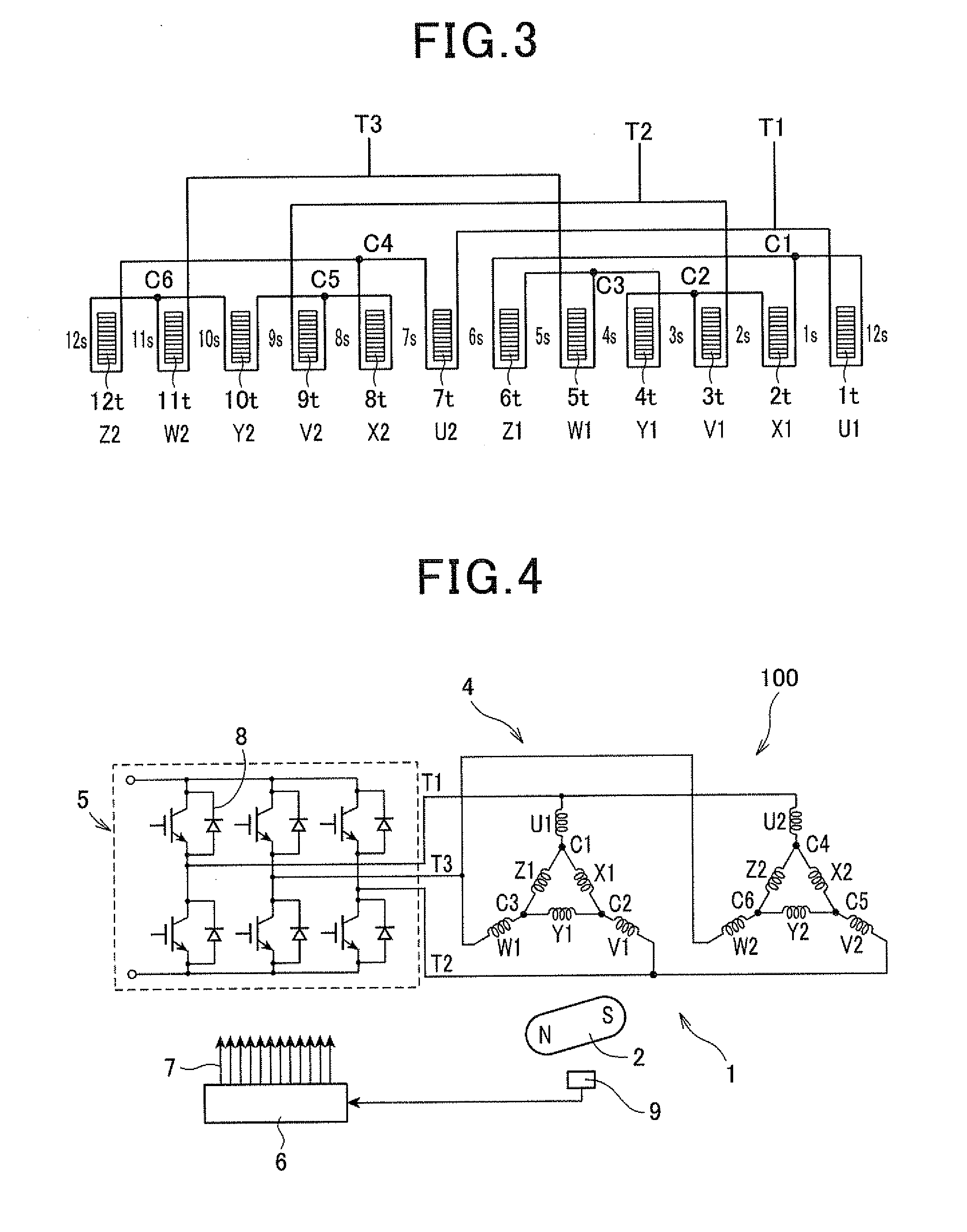
[0038]Referring further to FIG. 2 together with FIG. 1, the stator 3 includes a hollow cylindrical stator core 30 and a stator coil 4 wound around the stator core 30. The stator core 30 has twelve stator core teeth 3a that are formed to protrude radially inward and arranged in the circumferential direction of the stator core 30 at a predetermined pitch. Between each circumferentially-adjacent pair of the stator core teeth 3a, there is formed a slot 3b. That is, the stator core 30 has twelve slots 3b formed between the stator core teeth 3a. The stator coil 4 is comprised of first and second winding groups 4a and 4b.
[0039]The rotor 2 is rotatably disposed radially inside of the stator core 30. The rotor 2 has ten magnetic poles 2a that are formed, for example by perm...
second embodiment
[0062]FIGS. 8 and 9 illustrate the configuration of an electric rotating machine 1 according to the second embodiment of the invention. It should be noted that for the sake of facilitating understanding, first and second winding groups 4a and 4b, which are actually mounted on the same stator core 30, are separately shown in FIG. 9.
[0063]As shown in FIGS. 8 and 9, the stator core 30 of the stator 3 and the rotor 2 in this embodiment are identical to those in the first embodiment. Accordingly, in this embodiment, the number of the stator core teeth 3a is equal to twelve; the number of the magnetic poles 2a is equal to ten; with respect to the pitch of the magnetic poles 2a in electrical angle being equal to n, the pitch of the stator core teeth 3a in electrical angle is equal to (1−⅙)π.
[0064]However, the stator coil 4 is wound around the stator core 30 in a different manner from that in the first embodiment. Specifically, in the present embodiment, the stator coil 4 is wound around th...
third embodiment
[0092]This embodiment illustrates an electric rotating machine 1 which has a stator coil arrangement slightly different from that according to the first embodiment.
[0093]The stator core 30 of the stator 3 and the rotor 2 in this embodiment are identical to those in the first embodiment. Accordingly, in this embodiment, the number of the stator core teeth 3a is equal to twelve; the number of the magnetic poles 2a is equal to ten; with respect to the pitch of the magnetic poles 2a in electrical angle being equal to n, the pitch of the stator core teeth 3a in electrical angle is equal to (1−⅙)π.
[0094]Referring to FIG. 10, in this embodiment, the stator coil 4 is comprised of first and second winding groups 4a and 4b. The first winding group 4a includes first and second X-phase windings X1 and X2, first and second Y-phase windings Y1 and Y2, and first and second Z-phase windings Z1 and Z2. The second winding group 4b includes first and second U-phase windings U1 and U2, first and second...
PUM
 Abstract
Description
Claims
Application Information
 - R&D
- Intellectual Property
- Life Sciences
- Materials
- Tech Scout
- Unparalleled Data Quality
- Higher Quality Content
- 60% Fewer Hallucinations
Browse by: Latest US Patents, China's latest patents, Technical Efficacy Thesaurus, Application Domain, Technology Topic, Popular Technical Reports.
© 2025 PatSnap. All rights reserved.Legal|Privacy policy|Modern Slavery Act Transparency Statement|Sitemap|About US| Contact US: help@patsnap.com


