

System and method capable of navigating and/or mapping any multi-dimensional space
- Summary
- Abstract
- Description
- Claims
- Application Information
AI Technical Summary
Benefits of technology
Problems solved by technology
Method used
Image

Examples
first embodiment
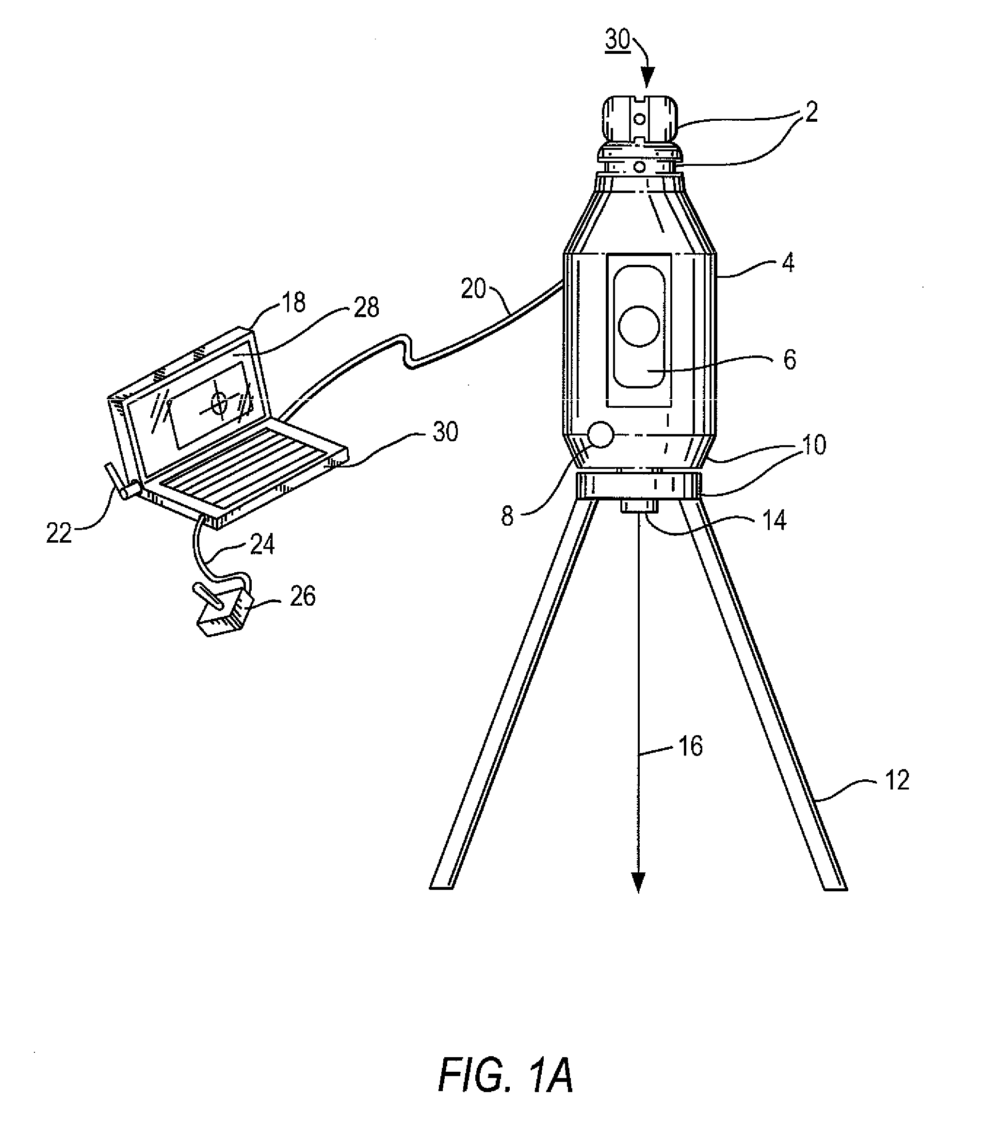
[0356]FIG. 49 shows a system comprising a total station 4902 (which is a stationary robotic device) comprising a tripod 4904, a laser range finder 4906, a wireless communications device 4908 located on top, and a housing 4910 containing, inter alia, computer and user interface circuitry. The robotic device 4902 moves the laser 4906 to constantly track a prism 4912 located on a pole 4914 which is similar to a surveyor's pole, except that it too has a wireless communications device 4916 located on its top. The total station 4902 knows the location of the prism 4912, and that location is communicated to a handheld device 4918 (e.g., a laptop computer or other processor) by the pole 4914 and the total station 4902. Should communication of the location of the prism 4916 be interrupted, the total station 4902 would institute a search pattern program in order to find the prism 4916. Once the position of the pole 4914 is ascertained, the handheld device 4918 can then triangulate its positio...
second embodiment
[0357]FIG. 50 shows a second embodiment wherein the total station 5000 (substantially similar to the total station 4902 in FIG. 49) points its laser beam 5002 generated by laser range finder 5004 at a target 5006, the location of which is determined by a user 5008 inputting coordinates into a handheld device 5010, and the coordinates are communicated wirelessly to the total station 5000. The user tells the handheld device the position where it wants the laser to illuminate, and the total station's laser beam is directed to that position.
third embodiment
[0358]FIG. 51 shows a third embodiment wherein the total station 5100 (substantially similar to total station 4908 of FIG. 49) comprising laser range finder 5126, tripod 5128 and assorted electronics and devices, locates a prism 5102 physically located on a mobile robot 5104 using laser range finder 5126 with beam 5130. The total station comprises software that executes the method of the present invention and which can direct the mobile robot 5104 to a specific location via wireless communications (i.e., using communication devices 5106 and 5108). The mobile robot 5104 is “blind,” but the total station 5100 navigates the robot 5104 to allow this mobile robot 5104 to perform directed movement. The mobile robot 5104 also comprises a wireless communications device 5108 and a laser 5110. The mobile robot's laser 5110 can then illuminate, with a laser beam 5112, any point location requested by the total station 5100. This is useful since the total station is stationary, and some location...
PUM
 Abstract
Description
Claims
Application Information