Dry-stack masonry system

a masonry system and dry-stack technology, applied in the direction of walls, building components, building repairs, etc., can solve the problems of difficult conversion of difficulty in converting wall units into end or corner units, and mortar exposed, etc., to achieve economic and simplified effects

Active Publication Date: 2011-03-03
WITCHER STEVE D
View PDF11 Cites 6 Cited by
  • Summary
  • Abstract
  • Description
  • Claims
  • Application Information

AI Technical Summary

Benefits of technology

[0016]The inventive dry stack block units and hardware system for constructing walls using the block units is designed to provide an aesthetically appealing, upscale brick or block landscaping wall. The walls may be erected as freestanding fencing or as low retaining walls of four feet or less in height. The improved block design cooperates with a truly unique hardware system that creates an economical and simplified system for bolting the wall together as it is erected. The wall may be built upon and bolted to a poured-in-place concrete footing, which may be engineered for various heights and applications with site specific-conditions, or it may be built on a simple footing so as to enable a thorough dry stack construction and thereby allow post construction modification or wholesale dismantling.
[0017]It is a principal object of the present invention to provide a new and improved dry-stack masonry building unit which simplifies and reduces the cost of mold design. The simplification has downstream effects of creating cost savings in the initial mold construction, extending the life of the mold, and yielding improved production results with fewer defects and rejected units.
[0018]Another object of the present invention is to provide an improved dry-stack building unit that simplifies wall construction by eliminating any need for the use of interlocking units and which requires only that the units be butted together. This saves time and effort and reduces damage to the block units during construction.

Problems solved by technology

Even so, due to the high cost and difficulty of constructing walls of quarried stone or block, cast cementitious blocks long ago replaced quarried stone as a preferred material in many applications.
However, mortarless cementitious cast block walls intended for permanent use usually require additional stability.
However, along with their advantages, the known cast blocks also have many disadvantages, including: difficulty in converting the wall units into end or corner units; lateral instability; vulnerability of exposed mortar to chemical or environmental degradation; expansion and contraction of mortar, causing cracking and separation of blocks; difficulty in constructing curved configurations; and vulnerability of broad flat surfaces to defacement and graffiti.
This made any wall built with the inventive system necessarily permanent and essentially impossible to change or modify after and during construction without damaging the block material.
Additionally, wall construction required labor skilled in the masonry and concrete trades.

Method used


Image

  • Dry-stack masonry system
  • Dry-stack masonry system
  • Dry-stack masonry system

Examples


Embodiment Construction

[0069]Referring to FIGS. 1 through 12B, wherein like reference numerals refer to like components in the various views, there is illustrated therein a new and improved dry stack masonry system.

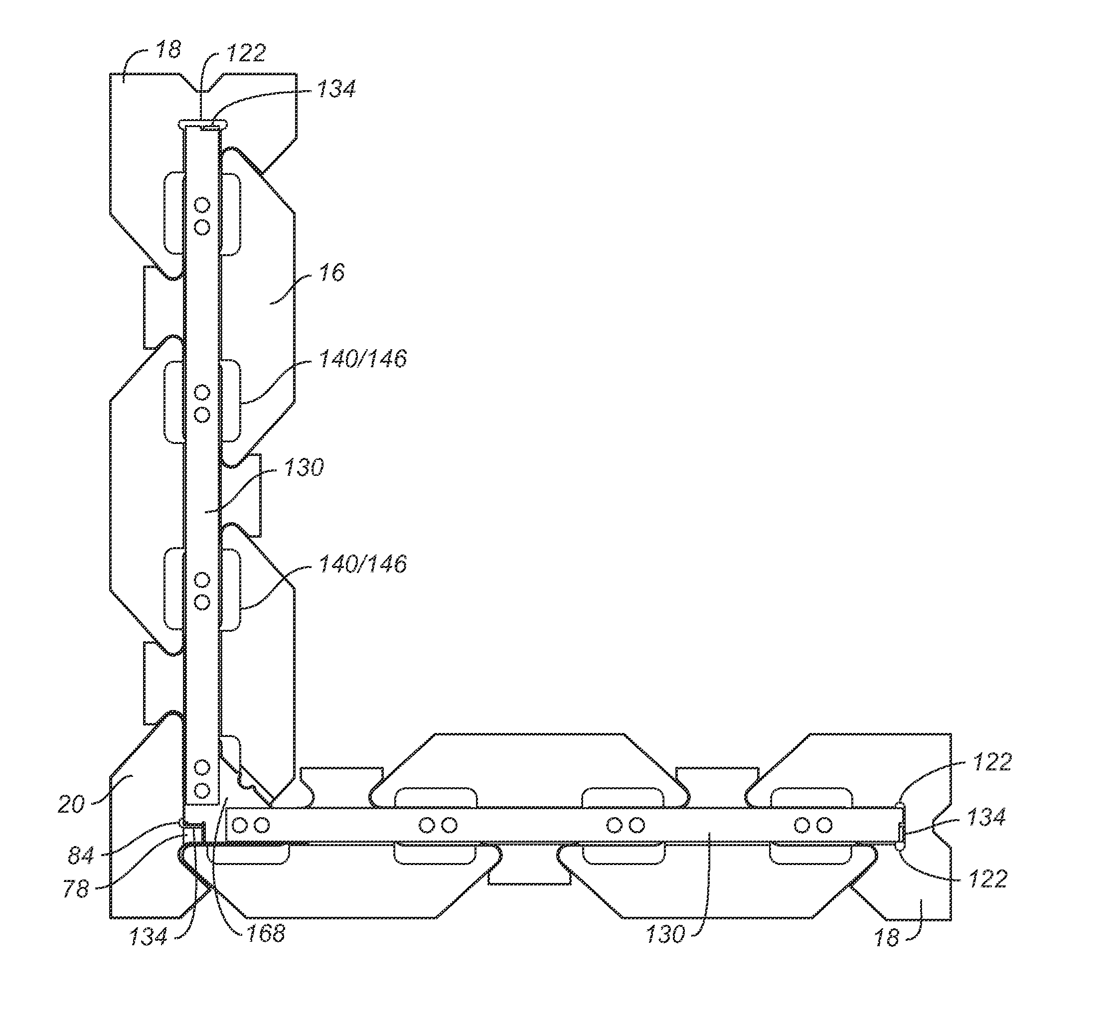
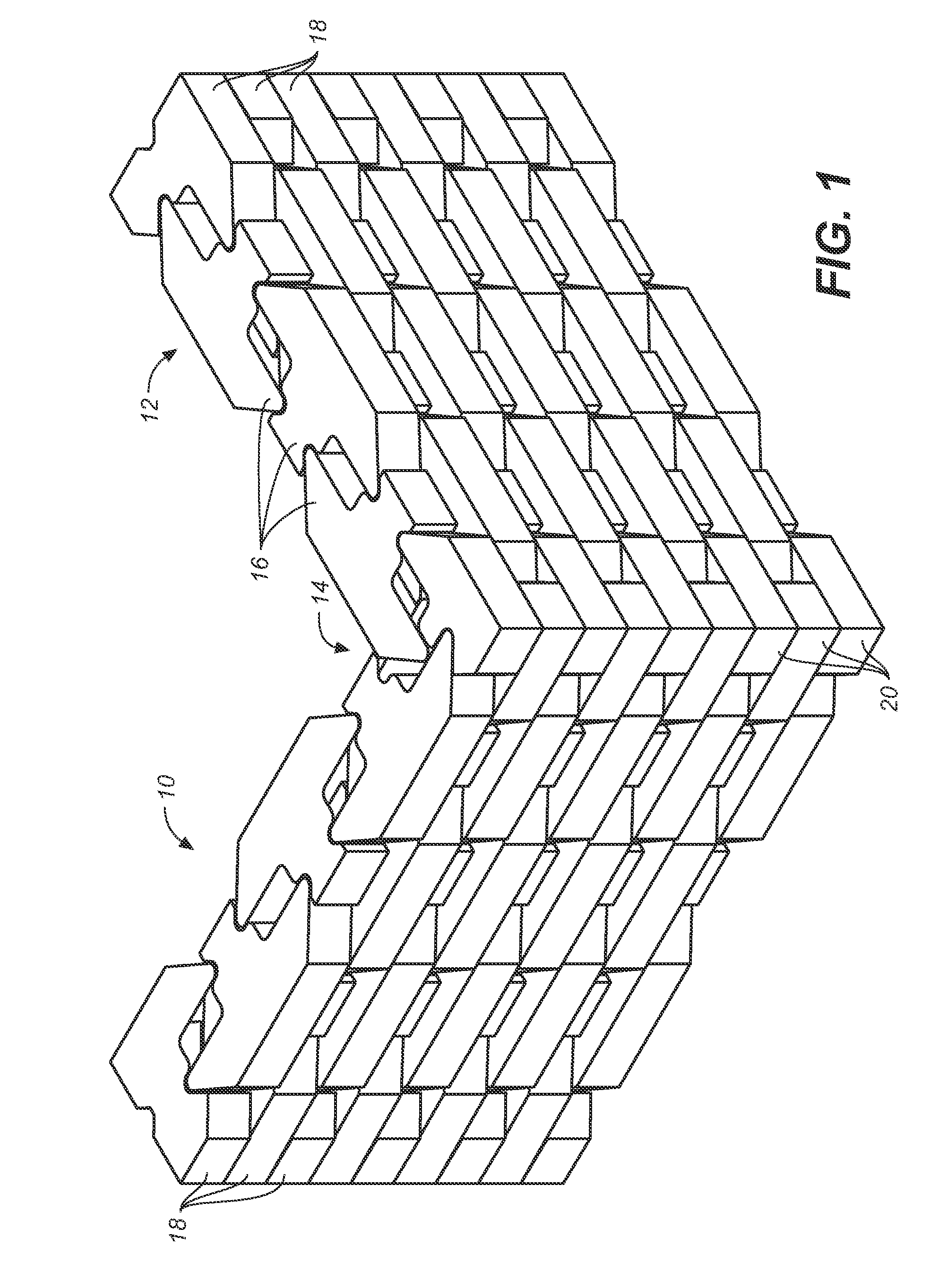
[0070]BLOCK UNITS: The inventive cementitious blocks and system for constructing walls using the same comprises, in the first instance, a unique combination of monolithic wall, corner, and end units. Two walls 10, 12, joined at a 90 degree corner 14, using the inventive system are shown in FIG. 1. As will be immediately appreciated from this view, a wall so constructed comprises three block units, including wall units 16, end units 18, and corner units 20.

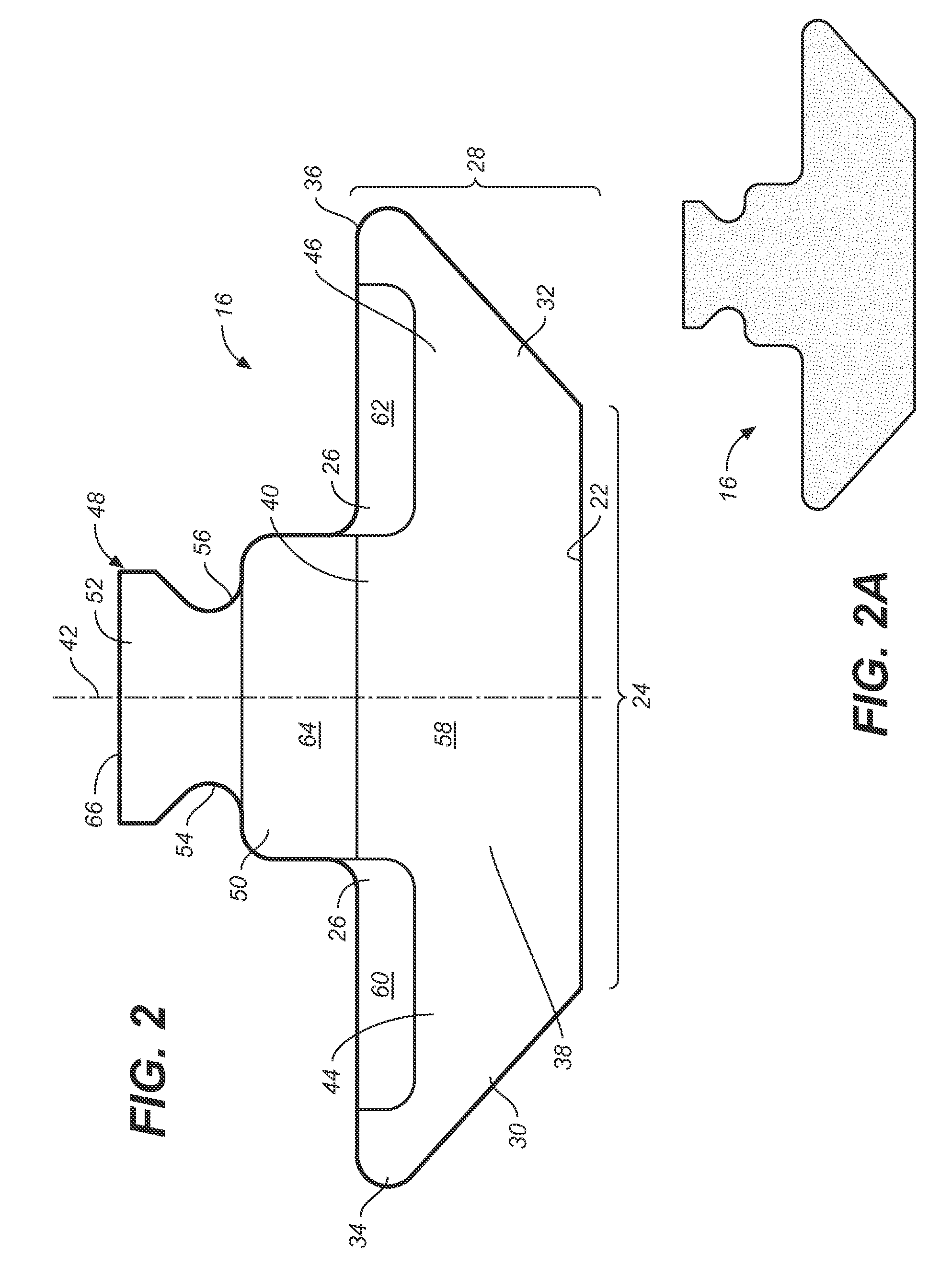
[0071]Referring now to FIGS. 2-2A, there is shown in schematic form a top plan view of the principle wall unit 16 of the inventive dry stack masonry block system. The wall unit includes a front face 22 having a front face width 24, a back side 26 and a depth 28 defined as the distance from the front face to the back side; and two angled sides ...


PUM


Abstract

A masonry block and hardware set for constructing dry stack walls and columns, including a wall unit, a corner unit, and an end unit, wherein each of said wall, corner, and end units have a top surface with a depression that is brought into substantial alignment when an adjoining block at the same level or in the same course is abutted with the respective unit, and further wherein when any two of said units are adjoined, said units create a vertically oriented space for accommodated clamping hardware, and further wherein each of said end and corner units include an alignment slot to align said end units and said corner units in relation to adjoining wall units. Clamping hardware is employed to bolt the wall while construction proceeds, the hardware being disposed in the masonry unit depressions and in the vertically oriented space created by stacked units. The clamping provides a downwardly directed compressive force and lateral rigidity.

Description

CROSS REFERENCES TO RELATED APPLICATIONS[0001]The present application claims the benefit of the filing date of U.S. Provisional Patent Application Ser. No. 61 / 239,659, filed Sep. 3, 2009 (Sep. 3, 2009).STATEMENT REGARDING FEDERALLY SPONSORED RESEARCH OR DEVELOPMENT[0002]Not applicable.THE NAMES OR PARTIES TO A JOINT RESEARCH AGREEMENT[0003]Not applicable.INCORPORATION-BY-REFERENCE OF MATERIAL SUBMITTED ON A COMPACT DISC[0004]Not applicable.SEQUENCE LISTING[0005]Not applicable.BACKGROUND OF THE INVENTION[0006]1. Field of the Invention[0007]The present invention relates to monolithic block-shaped wall construction units, such as masonry blocks, and more specifically to an improved stackable wall and column construction units adapted for use in constructing dry-stackable structures.[0008]2. Discussion of Related Art including information disclosed under 37 CFR §§1.97, 1.98[0009]The art of building dry stack stone walls is ancient and therefore highly developed. Even so, due to the high...

Claims


Application Information

Patent Timeline
Patent Type & Authority Applications(United States)
IPC IPC(8): E04C3/30E04B1/04E04B1/38E04B2/08
CPCE04C1/395E04B2002/0254E04B2002/0297
Inventor WITCHER, STEVE D.
Owner WITCHER STEVE D
Why Eureka
Try Eureka