Power cylinder non-metallic liner seal assembly

a non-metallic liner and assembly technology, applied in mechanical equipment, transportation and packaging, other domestic objects, etc., can solve the problems of imposing extreme hydrostatic pressures against which pneumatic or hydraulic pressure must work, affecting the work efficiency of the cylinder, and affecting the operation of the cylinder

Inactive Publication Date: 2002-05-28
THE UNITED STATES OF AMERICA AS REPRESENTED BY THE SECRETARY OF THE NAVY
View PDF7 Cites 3 Cited by
  • Summary
  • Abstract
  • Description
  • Claims
  • Application Information

AI Technical Summary

Problems solved by technology

In particular, in numerous structures common on submersible vessels, such as launchers for various payloads, depth of submersion of the vessel may impose extreme hydrostatic pressures against which pneumatic or hydraulic pressure must work.
However, CuNi material is subject to crevice corrosion when in contact with sea water for extended periods of time.
Such corrosion causes pitting of the inner bore of the cylinder.
The pitted cylinder cannot be effectively sealed by structures provided on the piston and roughness due to such pitting may cause damage to the seals when the piston is moved.
Since the portion of the cylinder through which the piston must move is generally exposed to sea water and often at high hydrostatic pressures, as pitting increases, the piston becomes less effective in maintaining a separation of sea water from the portion of the inner bore of the cylinder to which pressure is applied.
Leakage of sea water into this portion of the cylinder causes catastrophic failure of the firing valve.
Failure of the firing valve will cause failure of a launch of payload apparatus which is potentially very expensive.
Repair of the firing valve is also expensive and inconvenient.
Repair at sea cannot generally be accomplished due to inaccessibility of the structure and the launch apparatus must generally remain non-functional until repairs can be accomplished.
Other metal and alloy materials tend to accelerate the progress of corrosion and many cannot withstand the pressures and other severe operational conditions of the impulse cylinder and piston arrangement, such as the friction of the piston against the inner cylinder bore.
However, as can readily be understood, the CuNi material of the liner sleeve is similarly subject to corrosion due to contact with sea water and the cycle of corrosion, leakage, catastrophic failure of the firing valve and replacement of the firing valve is repeated.
Therefore, such corrosion presents a very substantial economic cost which has not been previously avoidable, particularly in the adverse conditions of the application and the extreme operating conditions of the cylinder and piston arrangement.
However, such applications do not involve withstanding high impulse pressures with minimal distortion or resisting abrasion as would occur in a reciprocating piston and cylinder assembly.
However, in such an application, long-term exposure to a corrosive liquid is not generally involved or a degree of corrosion can be tolerated in view of ease of repair.
However, such lubrication cannot be accomplished in the presence of long-term exposure to a corrosive liquid which will wash away any such material from the cylinder walls.
The gas or water pockets are driven along the interface between the metal and coating by the piston leading to peeling of the coating.
Additionally, since mine props require a pressure differential to be applied across the piston for extended periods of time, a step deformation occurs due to the radial elasticity of the thermoplastic coating material.
This step deformation damages ring seals which are used on the piston.
Such an approach may be acceptable in such an application in which pressure is applied for long periods of time and changes in pressure are gradual but is not suitable for extreme impulse pressures.
A coating, by its method of application (even if as a preformed sleeve) and, in the case of Heiliger, in-situ curing cannot achieve the high degree of structural integrity required when high impulse pressures are repeatedly applied, as in an internal combustion engine or an impulse cylinder for a payload launcher in a submersible vessel described above.

Method used


Image

  • Power cylinder non-metallic liner seal assembly
  • Power cylinder non-metallic liner seal assembly

Examples


Embodiment Construction

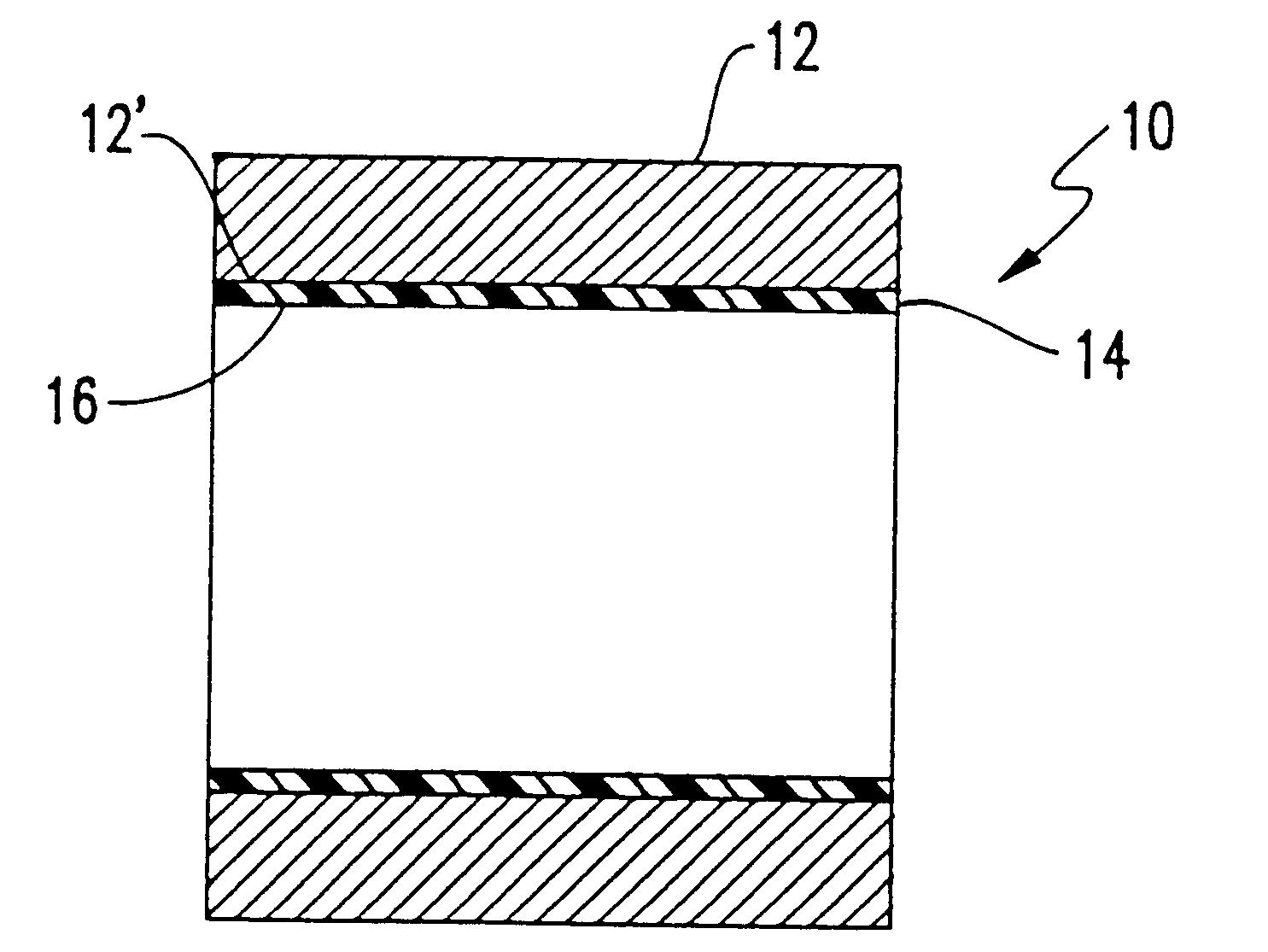
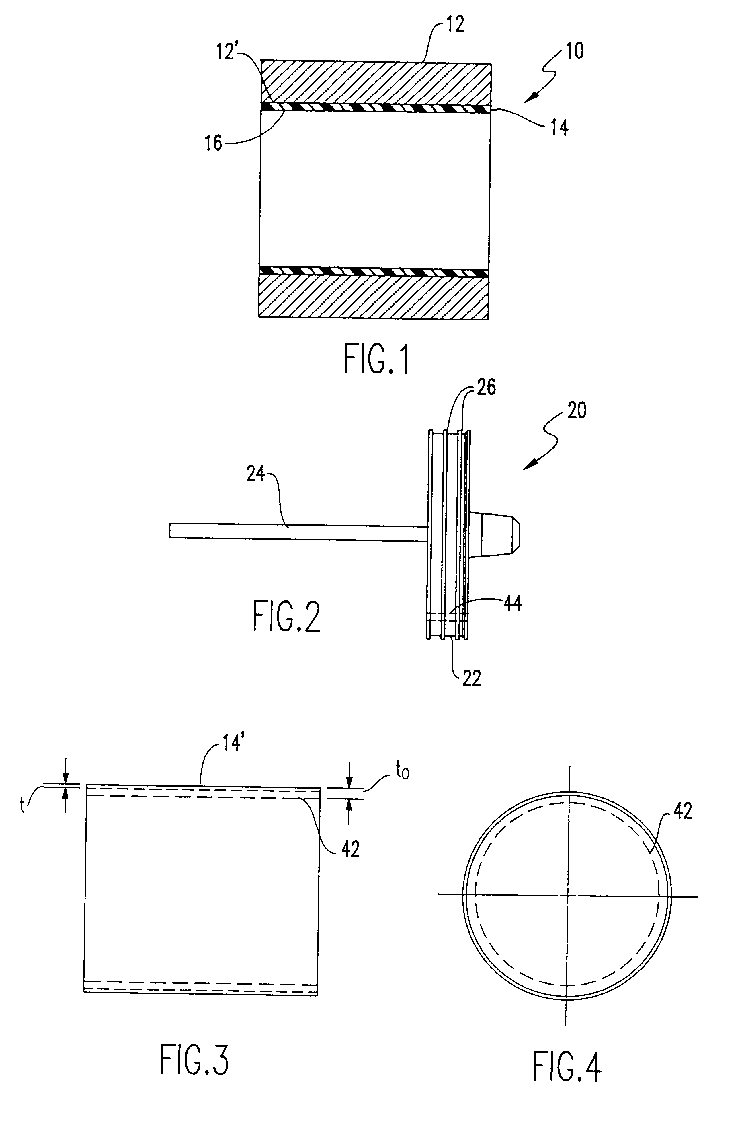
Referring now to the drawings, and more particularly to FIG. 1, there is shown a cross-sectional view of a cylinder assembly 10 including an outer cylinder 12 and liner 14 in accordance with the invention. Outer cylinder 12 is preferably cast of copper / nickel (CuNi) alloy and the inner bore 12' machined to a diameter slightly (preferably somewhat less than about one-eighth inch) larger than the desired final diameter of the inner bore 16 of the assembly 10. The outer surface of the outer cylinder 12 is not critical to the practice of the invention and various features such as mounting bosses can be integrally formed therewith. The thickness of the outer cylinder 12 is similarly not critical to the invention and can be sized to withstand anticipated pressures for a particular application by those skilled in the art.

It is to be understood that the proportions of FIG. 1, as shown, including a length of about twelve inches and an inner bore diameter of about nine inches, reflect those o...


PUM

PropertyMeasurementUnit
temperaturesaaaaaaaaaa
velocityaaaaaaaaaa
thicknessaaaaaaaaaa

Abstract

Corrosion resistance is provided for a power cylinder by providing a preloaded molded urethane elastomer sleeve liner within an outer cylinder of material such as a copper/nickel alloy which is subject to corrosion from long-term exposure to ambient fluids such as sea water. Preloading is preferably provided by thermal shrink fitting of the molded urethane sleeve liner to the inner bore of an outer metal cylinder. Preloading of a structure which has high structural integrity and low permeability thus effectively prevents incursion of fluids and gases at the interface between the outer cylinder and the sleeve liner as well as providing a surface which can be machined to a high degree of smoothness and against which reciprocating piston seals and wear assemblies can directly ride and which is resistant to abrasion therefrom even at high piston speeds.

Description

(1) Field of the InventionThe present invention generally relates to cylinder and reciprocating piston assemblies for use under high pressure in high ambient pressure environments and, more particularly, to such assemblies which are exposed over long periods of time to corrosive liquids such as sea-water.(2) Description of the Prior ArtMany ocean-going vessels and submarines, in particular, commonly include movable structures which require hydraulically or pneumatically derived forces to be applied in order to achieve the desired motion, either due to the size or mass of the movable structure, the speed of motion or acceleration to be achieved, static or dynamic pressures resisting such motion or because of inaccessibility of the structure to personnel. In some cases, high pressure air or steam can-be directly applied to portions of the structure to develop necessary forces. In other cases, cylinder and piston assemblies driven by high pressure air or steam are required in order to ...

Claims


Application Information

Patent Timeline
Patent Type & Authority Patents(United States)
IPC IPC(8): F15B21/00F15B15/14F15B15/00F15B21/06
CPCF15B15/1428F15B21/06Y10T428/1393Y10T428/1397
Inventor MCGRATH, JAMES E.VENIER, NICHOLAS O.
Owner THE UNITED STATES OF AMERICA AS REPRESENTED BY THE SECRETARY OF THE NAVY
Why Eureka
Try Eureka