Exhaust system, a saddle riding type vehicle having the same, and a method of manufacturing and mounting an exhaust pipe

a technology of exhaust pipe and exhaust pipe, which is applied in the direction of machines/engines, other domestic objects, mechanical apparatus, etc., can solve the problems of low productivity, corrosion of the exhaust pipe, and difficulty in making the sensor or the like penetrate the inner pipe in a gas-tight state, so as to achieve the effect of never lowering the working efficiency of installing the exhaust pipe, and never lowering the productivity of the exhaust pip

Active Publication Date: 2011-03-03
YAMAHA MOTOR CO LTD
View PDF7 Cites 10 Cited by
  • Summary
  • Abstract
  • Description
  • Claims
  • Application Information

AI Technical Summary

Benefits of technology

[0048]As a result, the end of the outer pipe including the third through-holes is fitted in the fitting portion of the exhaust system member. Thus, the exhaust pipe can conveniently be connected to the exhaust system member. The fitting portion is welded in a gas-tight state to the outer surface of the outer pipe inserted. Thus, the fitting portion acts also as the seal member. With such fitting portion provided, the exhaust system member and exhaust pipe can be connected simultaneously during sealing of the third through-holes, thereby never lowering the working efficiency in installing the exhaust pipe. Further, the fitting portion fixed by welding can realize a strong seal member not influenced by vibration or shocks of connection.
[0049]The third through-holes have a function to drain a liquid from the space between the outer pipe and the inner pipe at a time of manufacturing the exhaust pipe, and are sealed after the liquid is drained. Thus, the liquid can be drained promptly from the space between the outer pipe and inner pipe at a manufacturing time, and thus productivity of the exhaust pipe is never lowered. The third through-holes are sealed after the liquid is drained. Thus, even if exhaust gas flows into the space between the outer pipe and inner pipe through an inner through-hole, the exhaust gas can be prevented from being discharged to the atmosphere.
[0050]An exhaust pipe for exhaust gas discharged from an engine, includes an inner pipe arranged to guide the exhaust gas and an outer pipe mounted outside of the inner pipe; wherein an inner through-hole communicating inside and outside of the inner pipe is provided in a peripheral surface of the inner pipe; and drain holes for draining a liquid from a space between the outer pipe and the inne

Problems solved by technology

However, the conventional example with such construction has the following problem.
In this case, it takes time to drain the treating liquid from this space, which will lower productivity.
The treating liquid remaining in this space will cause corrosion of the exhaust pipe.
However, it is difficult to make the sensor or the like penetrate the inner

Method used


Image

  • Exhaust system, a saddle riding type vehicle having the same, and a method of manufacturing and mounting an exhaust pipe
  • Exhaust system, a saddle riding type vehicle having the same, and a method of manufacturing and mounting an exhaust pipe
  • Exhaust system, a saddle riding type vehicle having the same, and a method of manufacturing and mounting an exhaust pipe

Examples


first preferred embodiment

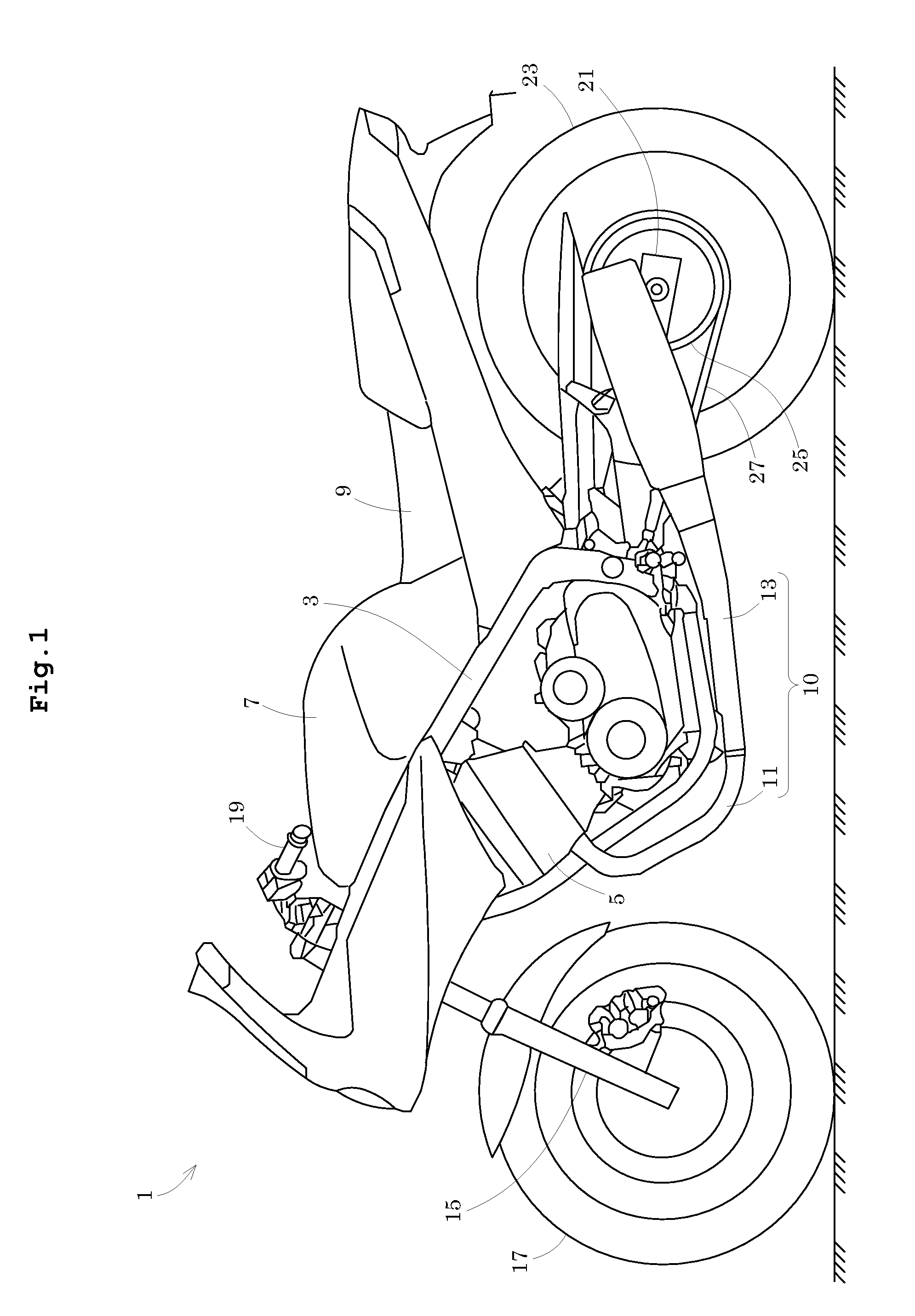
[0070]FIG. 1 is a side view showing an outline construction of a two-wheeled motor vehicle according to a preferred embodiment of the present invention. In FIG. 1, the left of the drawing is the front of a two-wheeled motor vehicle 1.

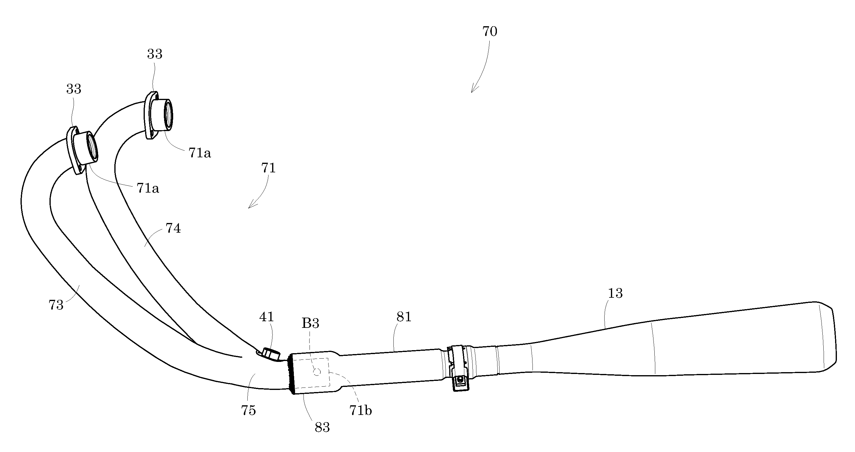
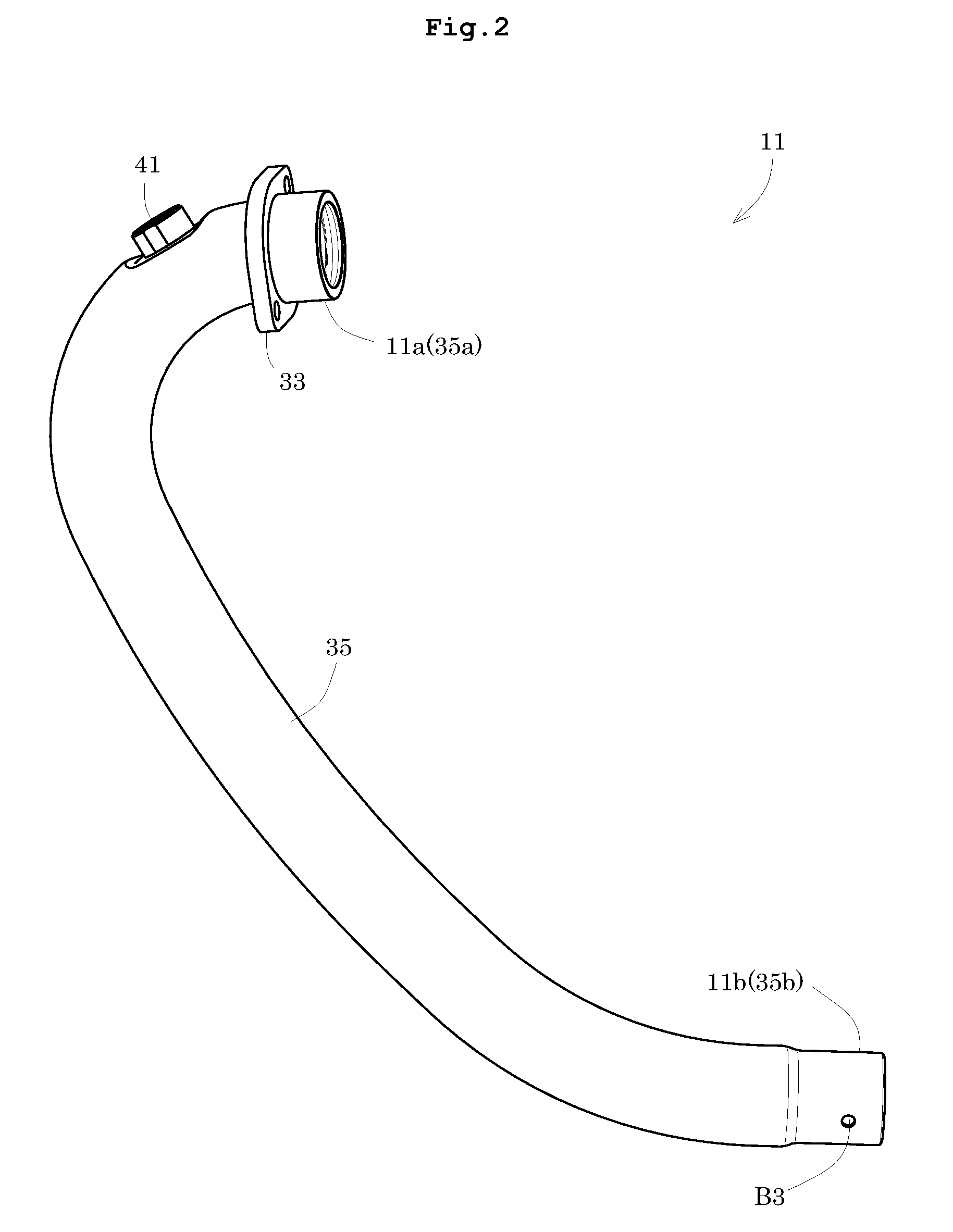
[0071]The two-wheeled motor vehicle 1 includes a main frame 3. The main frame 3 has an engine 5, a fuel tank 7, a seat 9 and so on fixed thereto. The engine 5 is disposed in a lower portion of the main frame 3. The engine 5 has an exhaust pipe 11 connected thereto. A muffler 13 is connected downstream of the exhaust pipe 11. The exhaust pipe 11 and muffler 13 constitute an exhaust system 10 for exhaust gas discharged from the engine 5.

[0072]A steering shaft (not shown) is rotatably supported at an upper front end portion of the main frame 3. A front fork 15 is connected to a lower portion of the steering shaft. A front wheel 17 is rotatably supported by lower portions of the front fork 15. A handlebar 19 is connected to an upper portion of the steering ...

second preferred embodiment

[0109]Next, Preferred Embodiment 2 of the present invention will be described with reference to the drawings. Since the construction of a two-wheeled motor vehicle 1 in Preferred Embodiment 2 is substantially the same as in Preferred Embodiment 1, the construction of the two-wheeled motor vehicle 1 according to Preferred Embodiment 2 will not be described. Components identical to those of Preferred Embodiment 1 are shown with the same signs, and will not particularly be described.

[0110]FIG. 11 is a sectional view of an exhaust system according to Preferred Embodiment 2. FIG. 12 is an appearance perspective view of the exhaust system according to Preferred Embodiment 2. An exhaust system 60 according to Preferred Embodiment 2 includes an exhaust pipe 61. An upstream end 61a of the exhaust pipe 61 is connected to the engine 5. A downstream end 61b of the exhaust pipe 61 is connected to the muffler 13. This exhaust pipe 61 has the outer pipe 35 and inner pipe 37. The first through-hole...


PUM

PropertyMeasurementUnit
Diameteraaaaaaaaaa
Elasticityaaaaaaaaaa
Heataaaaaaaaaa

Abstract

An exhaust system includes an exhaust pipe. The exhaust pipe includes an outer pipe and an inner pipe. A first through-hole and a second through-hole are provided in a peripheral surface of the outer pipe and a peripheral surface of the inner pipe, respectively, to receive an exhaust gas detector. Third through-holes are provided in the peripheral surface of the outer pipe, at a different position than that of the first through-hole. Since the third through-holes are provided in the outer pipe, a liquid can be drained promptly from a space between the outer pipe and inner pipe. Exhaust gas can be prevented from being discharged to the atmosphere by sealing the third through-holes.

Description

BACKGROUND OF THE INVENTION[0001]1. Field of the Invention[0002]The present invention relates to an engine exhaust pipe, an engine exhaust system, and a saddle riding type vehicle including an exhaust system and exhaust pipe, and a method of manufacturing and mounting an engine exhaust pipe, and more particularly relates to a technique of preventing exhaust gas from leaking from an exhaust pipe, without lowering productivity of the exhaust pipe.[0003]2. Description of the Related Art[0004]With a saddle riding type vehicle represented by a two-wheeled motor vehicle and the like, an engine exhaust pipe may be visible as part of its outward appearance. Therefore, the outward appearance may be improved by applying surface treatment such as chrome plating to the exhaust pipe. In this case, the exhaust pipe can be made into a hollow double structure having an outer pipe and an inner pipe, to prevent the surface of the outer pipe from discoloring due to the temperature of exhaust gas, ther...

Claims


Application Information

Patent Timeline
IPC IPC(8): F01N1/00B21D51/16
CPCF01N13/18F01N2470/24F01N13/008Y10T29/49398F01N13/141F01N2590/04F01N2450/20
Inventor ADACHI, MAKOTO
Owner YAMAHA MOTOR CO LTD
Why Eureka
Try Eureka