
Out-of-band radio link protocol and network architecture for a wireless network composed of wireless terminals with millimetre wave frequency range radio units

a technology of wireless terminals and network architecture, applied in the field of telecommunications, can solve problems such as limiting the operation range, blocking the transmission of content sources, and definition content streaming applications which are very sensitive to delays

Active Publication Date: 2011-03-03
SONY CORP
View PDF16 Cites 233 Cited by
  • Summary
  • Abstract
  • Description
  • Claims
  • Application Information

AI Technical Summary

Benefits of technology

[0014]The object of the present invention is to overcome the previously mentioned problems and to propose a possibility to exchange control and measurement data in a robust and secure mode.
[0018]The invention provides for a very robust solution since the back channel in form of the second out-of band wireless channel is omnidirectional, is uncoupled from the delay sensitive consumer data channel, has a greater range and penetrates obstacles to a greater extent than mm-waves. Subsequently, in order to maintain a steady data flow via the directional antennas the proposed out-of-band channel can provide important control data in a timely fashion, even if temporal obstructions hamper the data transmission between the directional antennas.

Problems solved by technology

The several GHz of bandwidth available in these bands, however, is accompanied by a severe free space path loss which limits the operation range.
However, the main problem with above approach consists in how to reliably sending back to the transmitter the measurements done at the receiver for every antenna beam combination in order to run the beam selection and tracking algorithms effectively.
On the other hand, even if no obstruction or any other channel degradation occurs in the directional data channel, sending additional control information over the same mm-wave channel can cause excessive delays if a retransmission of data is necessary, eventually blocking the content source transmission.
This is particularly an issue in high definition content streaming applications which are very sensitive to delays, since some control information has to be exchanged between the data source and the data consumer like HDCP (High bandwidth Digital Content Protection).
Therefore, for at least the above reasons, it is not recommendable to use the same antenna link for sending back control and measurement data, because this channel may not be very robust due to sudden obstructions, the sent back control data may create unacceptable delays in streaming the user data (e.g. movie) and lastly, subjects consumer electronic devices to the heavy burden of implementing costly two way radios.

Method used


Image

  • Out-of-band radio link protocol and network architecture for a wireless network composed of wireless terminals with millimetre wave frequency range radio units
  • Out-of-band radio link protocol and network architecture for a wireless network composed of wireless terminals with millimetre wave frequency range radio units
  • Out-of-band radio link protocol and network architecture for a wireless network composed of wireless terminals with millimetre wave frequency range radio units

Examples


Embodiment Construction

[0034]In the following description, the present invention is explained in more detail in relation to the enclosed drawings in which

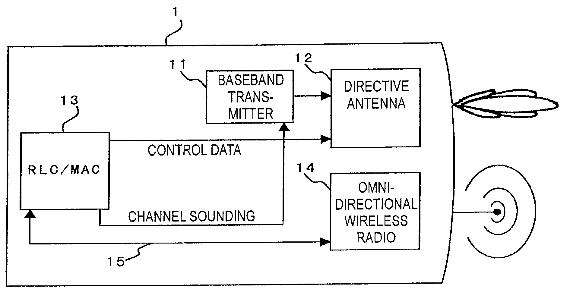
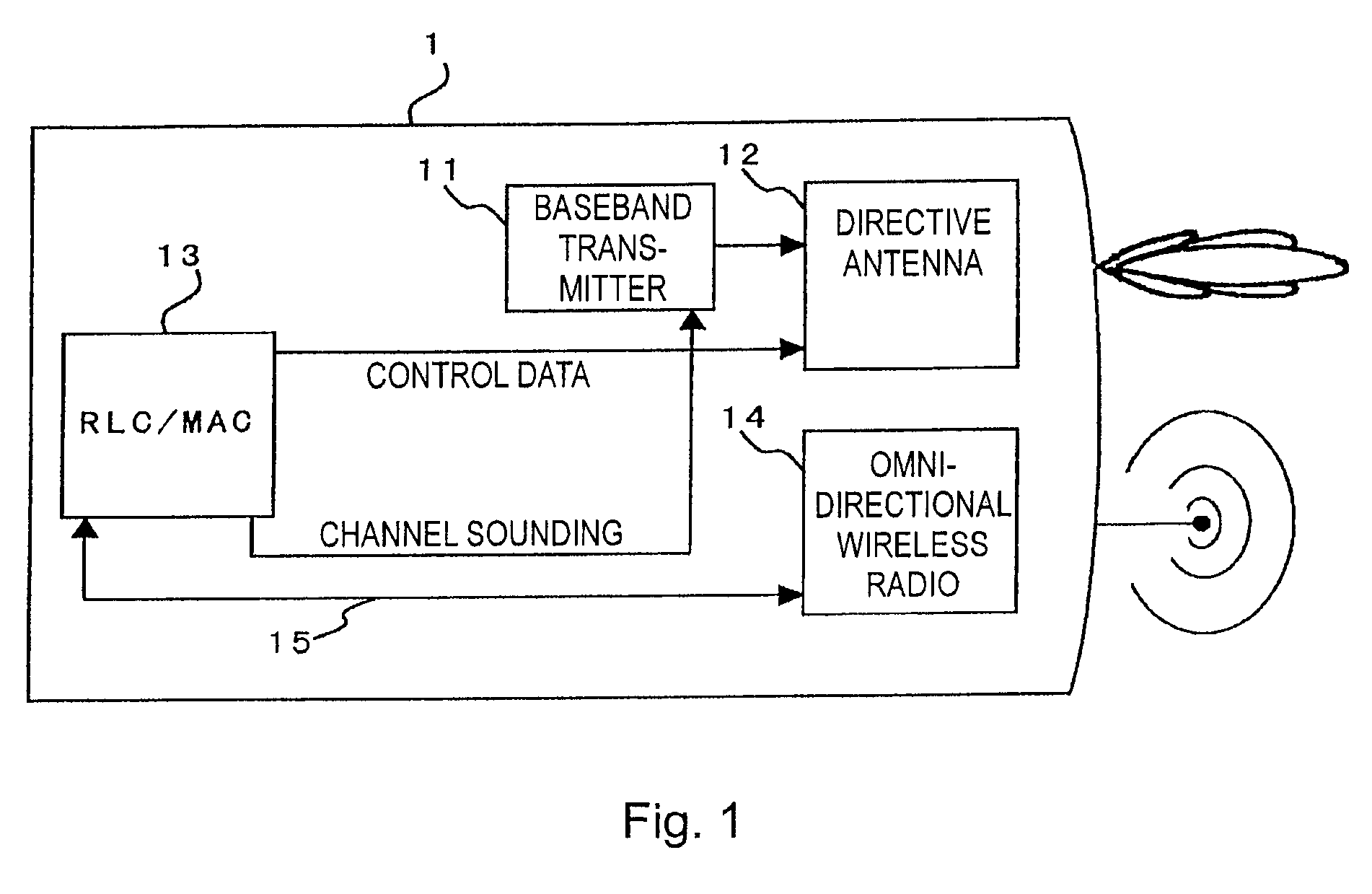
[0035]FIG. 1 shows a wireless transmitter terminal with a directional and an omnidirectional antenna.

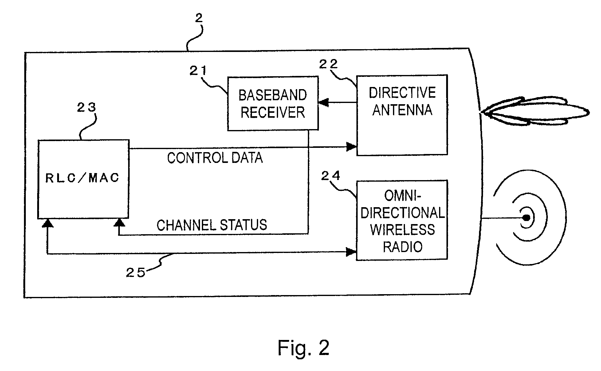
[0036]FIG. 2 shows a wireless receiver terminal with a directional and an omnidirectional antenna.

[0037]FIG. 3 shows a wireless relay with a first and a second directional and an omnidirectional antenna.

[0038]FIG. 4 shows the process of selecting a useful beam combination between two embodiments of a wireless transmitter terminal and a wireless receiver terminal.

[0039]FIG. 5 shows the process of beam tracking.

[0040]FIG. 6 shows the process of sounding data transmission channels.

[0041]FIG. 7 shows the process of collaborative beam selection.

[0042]FIG. 8 shows a transmission scenario in a home network environment.

[0043]It is to be understood that only elements important for the understanding of the present invention are shown in the drawings. Further elemen...


PUM


Abstract

The present invention relates to a wireless transmitter comprising a transmitter radio unit working a wireless transmitter comprising a transmitter radio unit working in the millimeter wave frequency band using a directional antenna and a bidirectional radio unit working in a frequency range different from said transmitter radio unit and using an omnidirectional antenna. The invention further relates to a wireless receiver and a wireless relay.

Description

[0001]TECHNICAL FIELD[0002]The present invention relates to the field of telecommunications, such as wireless terminals with millimetre wave radios, in particular it relates to novel wireless terminals using directional antennas and omnidirectional antennas for seamless high data transmission.BACKGROUND ART[0003]The continuously increasing demand for higher bandwidth in the actual non-licensed wireless communication systems, aiming to transmit high resolution video streams which need data rates in the multi-GBbps ranges forced a search for frequency ranges where such a bandwidth is available like the unlicensed 60 GHz ISM band also known as millimetre wave band (mm-wave) or other unlicensed frequency bands.[0004]The several GHz of bandwidth available in these bands, however, is accompanied by a severe free space path loss which limits the operation range. Furthermore, mm-waves do not pass through objects or people. Hence, mm-waves will not penetrate walls and a person passing throug...

Claims


Application Information

Patent Timeline
IPC IPC(8): H04B7/14H04B1/04H04B1/06
CPCH04W24/02H04B7/1555
Inventor NOGUEIRA-NINE, JUAN
Owner SONY CORP
Learn More