Cell Configuration for Self-Organized Networks with Flexible Spectrum Usage
- Summary
- Abstract
- Description
- Claims
- Application Information
AI Technical Summary
Benefits of technology
Problems solved by technology
Method used
Image
Examples
first embodiment
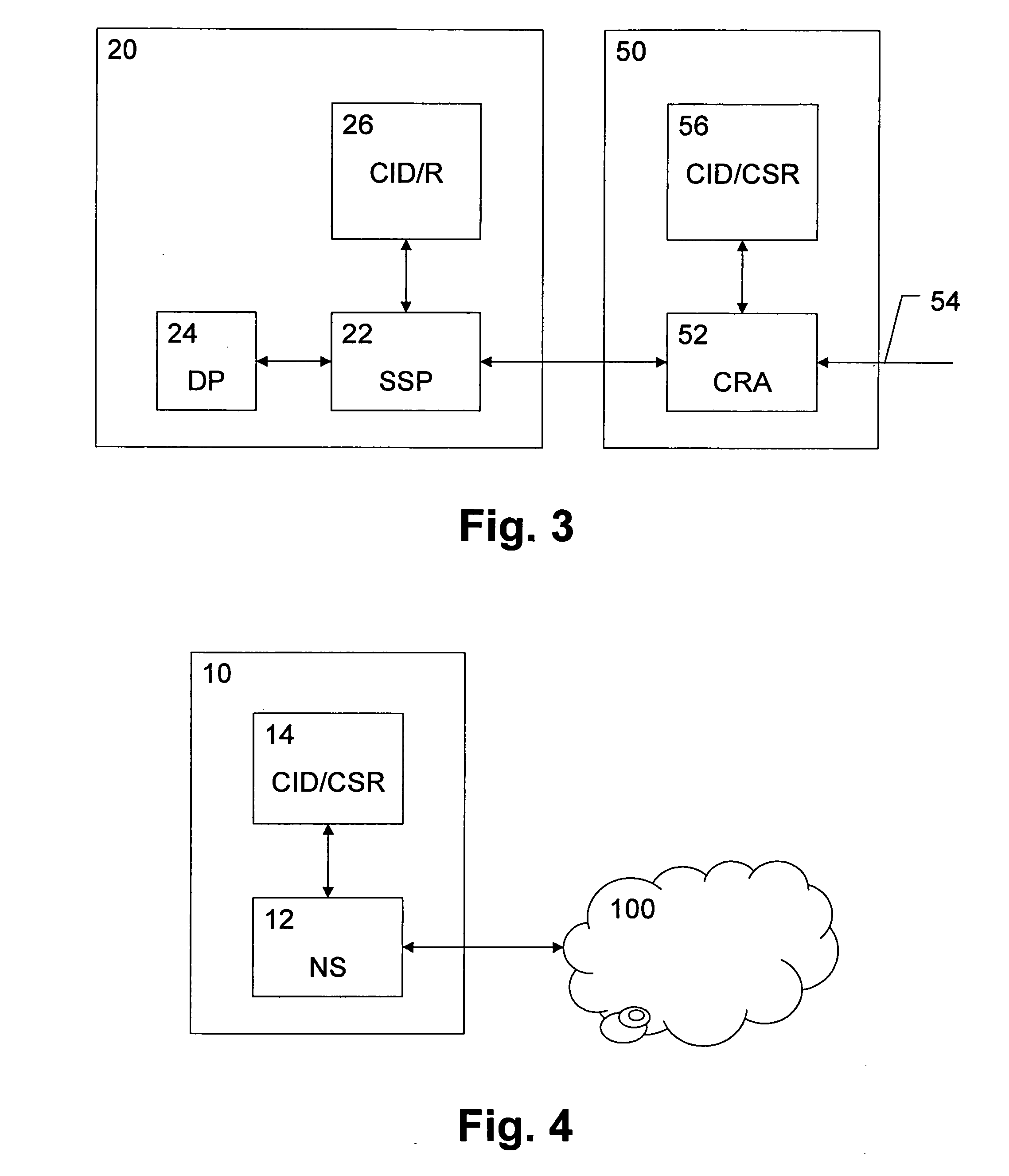
[0055]FIG. 3 shows a schematic block diagram of a PBCSR entity 20 and a central control entity 50 according to a The central control entity 50 may correspond to the network control entities 31, 32 of FIG. 1.
[0056]The PBCSR entity 20 can have a unique identity assigned. For implementation alternatives, the PBCSR entities 20 may consist of a mutually exclusive semi-static part (SSP) 22 (based on e.g. an orthogonal frequency and / or time division) and a dynamic sharable part (DP) 24 (which can be adapted to allocate or configure the rest of the available system bandwidth or spectrum resources seen by a given cell). The mutually exclusive semi-static part 22 of the PBCSR entity 20 may be adapted or designated to accommodate at least all semi-static instances of cell-specific common and control channels. The dynamic sharable part 24 of the PBCSR entity 20 may be adapted to provide highest possible data rates and optimal resource utilization by means of efficient FSU. Furthermore, a stora...
second embodiment
[0080]FIG. 7 shows a schematic processing and signaling diagram of a cell configuration procedure where the access device performs self-selection of PLCID and PBCSR.
[0081]Based on the sensing results obtained in an initial sensing step 1, the access device 10 selects in step 2 a PLCID from an unused set of predefined PLCIDs and PBCSR mapped on the selected PLCID. This mapping relationship can be stored for example in the storing unit 14 of FIG. 4. The access device then optionally notifies and confirms the selected PLCID and PBCSR with towards network (e.g. to the central control entity 50) in step 3 to get the final PLCID, PBCSR and global cell ID configured from the network. In step 4, the assigned PBCSR entity 20 is notified about its assignment to the PLCID. In response thereto, the PBCSR entity 20 allocates suitable cell spectrum resources to the PLCID in step 5. Finally, in step 6, the central control entity 50 responds to the access device 10 with the assigned PLCID, global ...
third embodiment
[0084]FIG. 10 shows a schematic block diagram of an alternative software-based implementation according to a The required functionalities can be implemented in any network entity 400 (which may be provided in the access device 10, the central control entity 50 or the PBCSR entity 20) with a processing unit 410, which may be any processor or computer device with a control unit which performs control based on software routines of a control program stored in a memory 412. The control program may also be stored separately on a computer-readable medium. Program code instructions are fetched from the memory 412 and are loaded to the control unit of the processing unit 410 in order to perform the processing steps of the above device-specific functionalities described in connection with FIGS. 3, 4, 6, and 7, which may be implemented as the above mentioned software routines. The processing steps may be performed on the basis of input data DI and may generate output data DO. In case of the a...
PUM
 Abstract
Description
Claims
Application Information
 - Generate Ideas
- Intellectual Property
- Life Sciences
- Materials
- Tech Scout
- Unparalleled Data Quality
- Higher Quality Content
- 60% Fewer Hallucinations
Browse by: Latest US Patents, China's latest patents, Technical Efficacy Thesaurus, Application Domain, Technology Topic, Popular Technical Reports.
© 2025 PatSnap. All rights reserved.Legal|Privacy policy|Modern Slavery Act Transparency Statement|Sitemap|About US| Contact US: help@patsnap.com


