Data modulation method, modulator, recording method, and recording apparatus

Inactive Publication Date: 2011-03-03
LG ELECTRONICS INC
View PDF8 Cites 16 Cited by
  • Summary
  • Abstract
  • Description
  • Claims
  • Application Information

AI Technical Summary

Benefits of technology

[0030]The present invention has advantages in that it does not require an auxiliary table for applying the k constraint and can easily make a change in the k constraint and can also prevent error transfer due to bit flip.
[0

Problems solved by technology

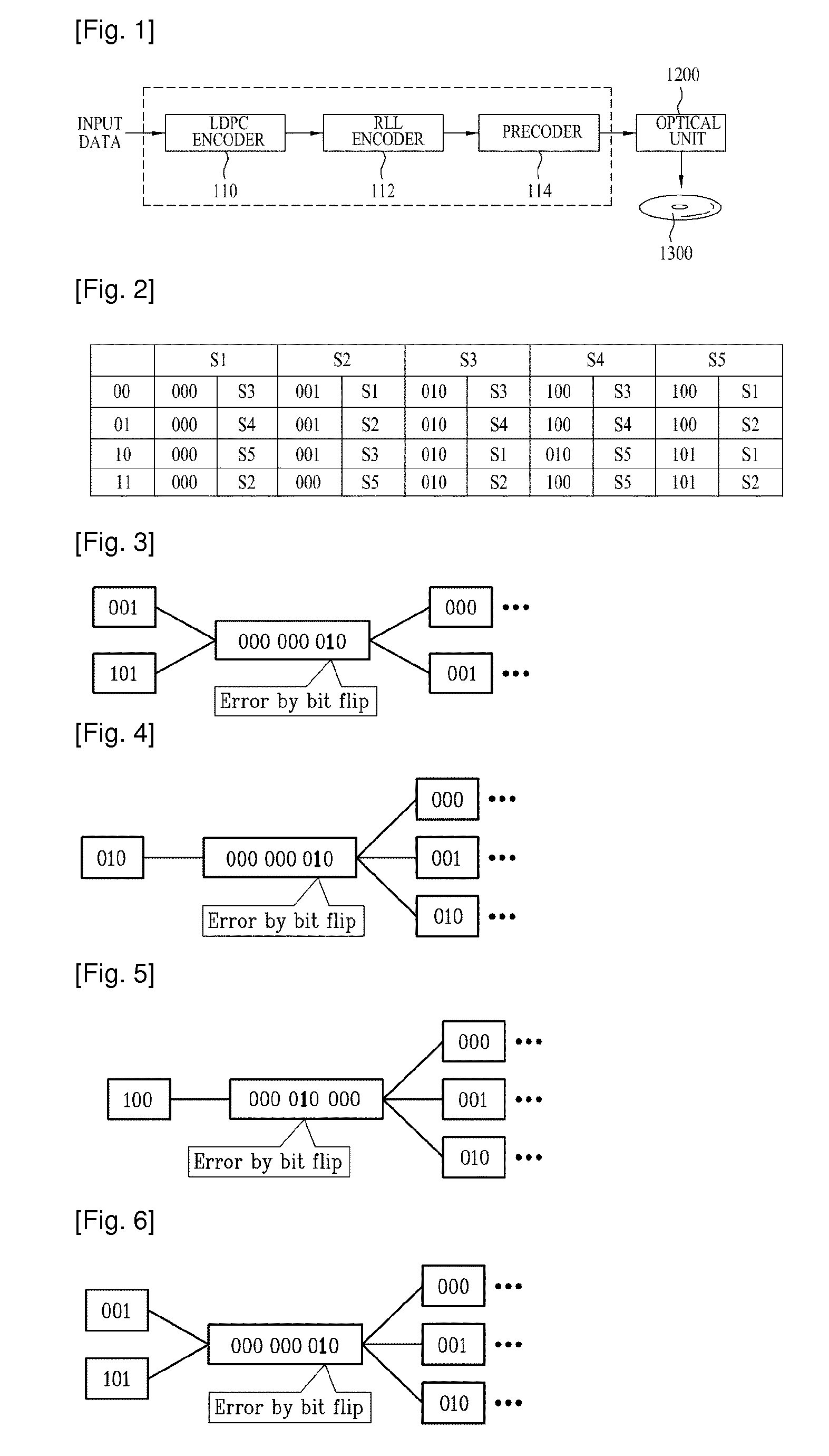
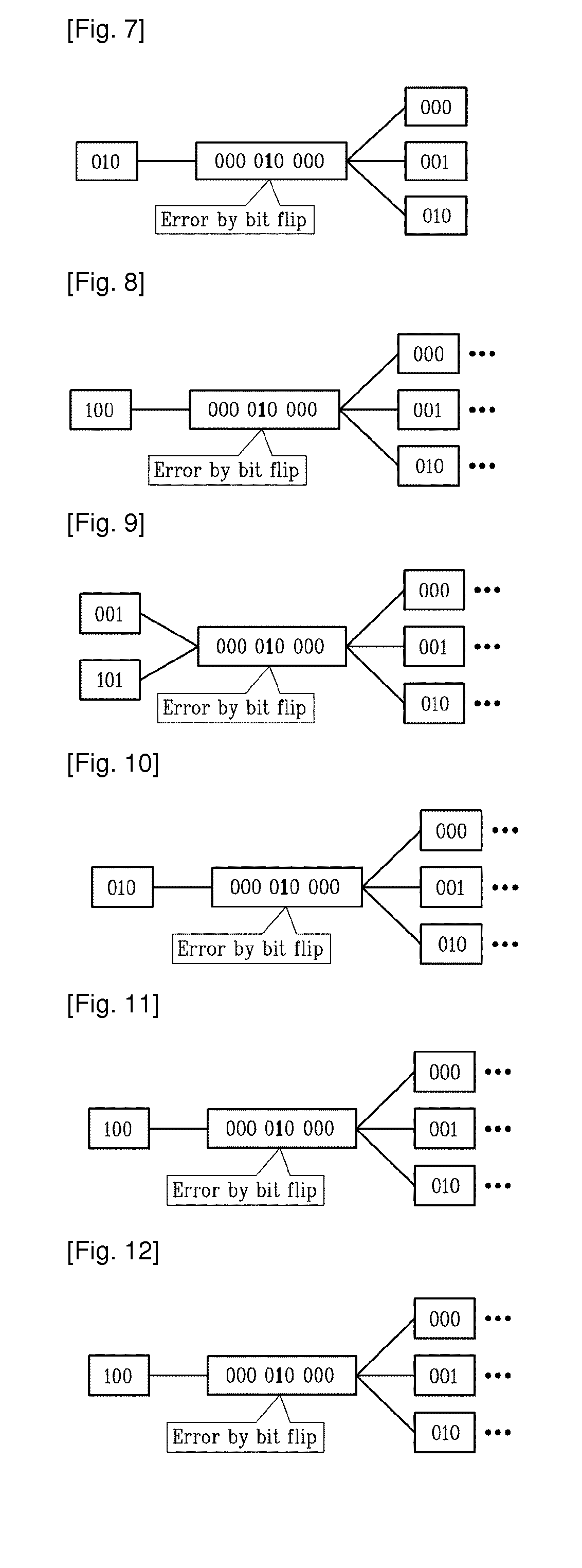
That is, the bit flip method adds an error to the channel sequence to apply the k constraint to the channel sequence.
In this method, an error is added to the channel sequence before it is recorded on a recording medium.
Therefore, the sequence to be recorded on the recording medium contains an error.
Thus, the bit flip method has problems in that it is difficult to reconstruct original data dur

Method used


Image

  • Data modulation method, modulator, recording method, and recording apparatus
  • Data modulation method, modulator, recording method, and recording apparatus
  • Data modulation method, modulator, recording method, and recording apparatus

Examples


first embodiment

[0161]FIG. 24 is a block diagram of the error correction apparatus 224 according to the present invention. As shown in FIG. 24, the error correction apparatus 224 according to this embodiment includes an error detection unit 2240, an error determination unit 2242, and an error correction unit 2244.

[0162]The error detection unit 2240 calculates a syndrome vector (S=CHT) from a parity check matrix H and determines whether or not an error has occurred in received data (i.e., detects an error in received data). Here, T denotes transposition.

[0163]The error determination unit 2242 determines whether or not an error bit detected at the error detection unit 2240 is an error due to bit flip. Here, the error determination unit 2242 checks the frequency of detection of each error bit and determines that an error bit detected with relatively high frequency is an error due to bit flip.

[0164]To determine whether or not the error bit is an error due to bit flip, the error determination unit 2242 ...

second embodiment

[0178]FIG. 29 is a flow chart illustrating a data error correction method according to the In the data error correction method according to this embodiment, repetitive decoding is performed a given number of times and signs of probability values associated with a bit position at which it is suspected that bit flip has occurred during the repetitive decoding procedure are converted. This method is described below in detail.

[0179]First, a received sequence C is decoded according to a sum-product algorithm (S200).

[0180]Next, a syndrome vector S of the sequence C is checked using a parity check matrix (S210) and it is determined whether or not the syndrome vector S is 0 (S220). Similar to the first embodiment, if the syndrome vector is 0, this indicates that no error has occurred in the received data or that no error has been detected although an error has occurred. Accordingly, in this case, data error correction is terminated and a next process for data reproduction is performed (S23...


PUM


Abstract

A data modulation method and a data error correction method are provided. The data modulation method includes generating a channel sequence for an input sequence, determining whether or not the channel sequence violates a Run Length Limit (RLL) constraint, and performing, when the channel sequence violates the RLL constraint, bit flip at a position prior to a position at which the RLL constraint is violated among positions of bits included in the channel sequence. The data error correction method includes detecting an error bit of received data using a parity check matrix, determining whether or not the error bit is an error caused by bit flip, and correcting the error bit when the error bit is an error caused by bit flip for applying an RLL constraint.

Description

TECHNICAL FIELD[0001]The present invention relates to a data modulation method, a modulator, a recording method, and a recording apparatus, and more particularly, to a method and apparatus for modulating data to be recorded on an optical recording medium and a recording method and apparatus using the same.[0002]The present invention also relates to a data error correction method and apparatus, and more particularly, to a method and apparatus for correcting an error in modulated data to be recorded on an optical recording medium.BACKGROUND ART[0003]A reproduction unit in a general recording system uses a modulation code to reduce distortion of a reproduced signal caused by interference between adjacent symbols and to achieve appropriate timing recovery.[0004]The modulation code can be represented by (d, k), which is referred to as a Run Length Limit (RLL) code. Here, “d” indicates the minimum number of 0s that can be present between 1s of the modulation code and is used as a constrai...

Claims


Application Information

Patent Timeline
IPC IPC(8): G06F11/16H03M13/15G06F11/10
CPCG11B7/0045G11B20/10055G11B2020/185G11B20/1833G11B20/1426
Inventor LEE, JUN
Owner LG ELECTRONICS INC
Why Eureka
Try Eureka