Jacket for impression cylinder or transfer cylinder and method for manufacturing the same

a technology of transfer cylinder and impression cylinder, which is applied in the direction of metal-working apparatus, printing press parts, printing, etc., can solve the problems of metal plate denting, bending, or bending, and requiring the shutdown of the printing press for a long time, and achieves good shape-maintaining properties, precise winding, and sufficient flexibility.

Inactive Publication Date: 2011-03-10
SHINODA
View PDF1 Cites 15 Cited by
  • Summary
  • Abstract
  • Description
  • Claims
  • Application Information

AI Technical Summary

Benefits of technology

[0008]In the present invention, because an ink smear preventive sheet having flexibility as a whole is formed by providing an ink smear preventive structure having a concave-convex surface on the surface of a flexible sheet substrate made of a resin and the composite structure which is to be formed into a jacket is completed by providing a flexible metal thin plate on the back surface of the ink smear preventive sheet, the jacket, in comparison to one according to Japanese Patent Laid-Open No. H8-12151, is not so thin as to dent or break (because of the two-layer structure, namely, ink smear preventive sheet layer and metal thin plate layer), has a good shape-maintaining property due to the presence of an ink smear preventive sheet without making the metal thin plate thicker, and, moreover, has sufficient flexibility as a whole. Thus, it is easy to wind the jacket around an impression cylinder or a transfer cylinder. Also, stretching of the ink smear preventive sheet is suppressed by the metal thin plate and any defects which might otherwise be caused by the thinness of the metal thin plate are compensated for by the ink smear preventive sheet. Thus, the jacket can adapt to the shape of the impression cylinder or the transfer cylinder better, making precise winding and a lighter work burden possible.
[0009]A method for manufacturing a jacket of the present invention comprises forming an ink smear preventive sheet having flexibility as a whole by providing an ink smear preventive structure having a concave-convex surface on a surface of a flexible sheet substrate made of a resin and winding the ink smear preventive sheet into the form of a roll; while pulling out the ink smear preventive sheet, superposing a metal thin plate on the back surface thereof; and pressing the sheet and the plate with an adhesive interposed between the superposing surfaces and cutting the pressed two-layer structure to a predetermined size. Thus, the ink smear preventive sheet manufactured beforehand can be wound and stored, and, therefore, the ink smear preventive sheet can be mass produced to reduce costs. Alternatively, the composite structure for the jacket can be manufactured by pulling out the sheet from a roll by a predetermined length according to need, superposing and pressing the sheet metal thin plate with an adhesive interposed therebetween, and cutting the thus formed composite structure to a size suitable for the jacket. Further, by regulating the gap between the press rolls used to press the sheet and plate together to a constant value at the time of pressing, a jacket having good thickness precision can be manufactured. Thus, in a multi color printing press such as one which prints four colors on one surface and four colors on the back surface, there will be no difference in the cylinder diameter between the respective impression cylinders. Alternatively, in a type where two jackets are installed on a periphery of an impression cylinder referred to as a double-diameter cylinder, the thickness of the two jackets is kept uniform and, thus, uniform printing becomes possible. Also, even when one jacket is damaged and is replaced with a new one, the jacket has uniformity with the remaining one, thus uneven printing does not occur.

Problems solved by technology

Even if a thermally sprayed layer having an average thickness of 30 to 80 μm could be formed by plasma spraying on a metal plate having a thickness of 0.1 mm (100 μm), there has been a fear that, when winding this metal plate around the impression cylinder or transfer cylinder, the metal plate might be dented, twisted, or bent, so that its back surface may not be pressed closely against the cylinder.
Further, when the metal plate is thick and has high hardness and high rigidity, the work of winding the plate around the cylinder has been a heavy burden and has required shutdown of the printing press for a long time.
Especially, with a cylinder having a diameter as small as about 180 mm, when the metal plate is thick and has small deflection, the winding work becomes increasingly difficult and, if the plate is forcedly wound, there is a fear that it may be damaged.

Method used


Image

  • Jacket for impression cylinder or transfer cylinder and method for manufacturing the same
  • Jacket for impression cylinder or transfer cylinder and method for manufacturing the same
  • Jacket for impression cylinder or transfer cylinder and method for manufacturing the same

Examples


Embodiment Construction

[0018]Hereinafter, preferable embodiments of the present invention will be described with reference to the drawings.

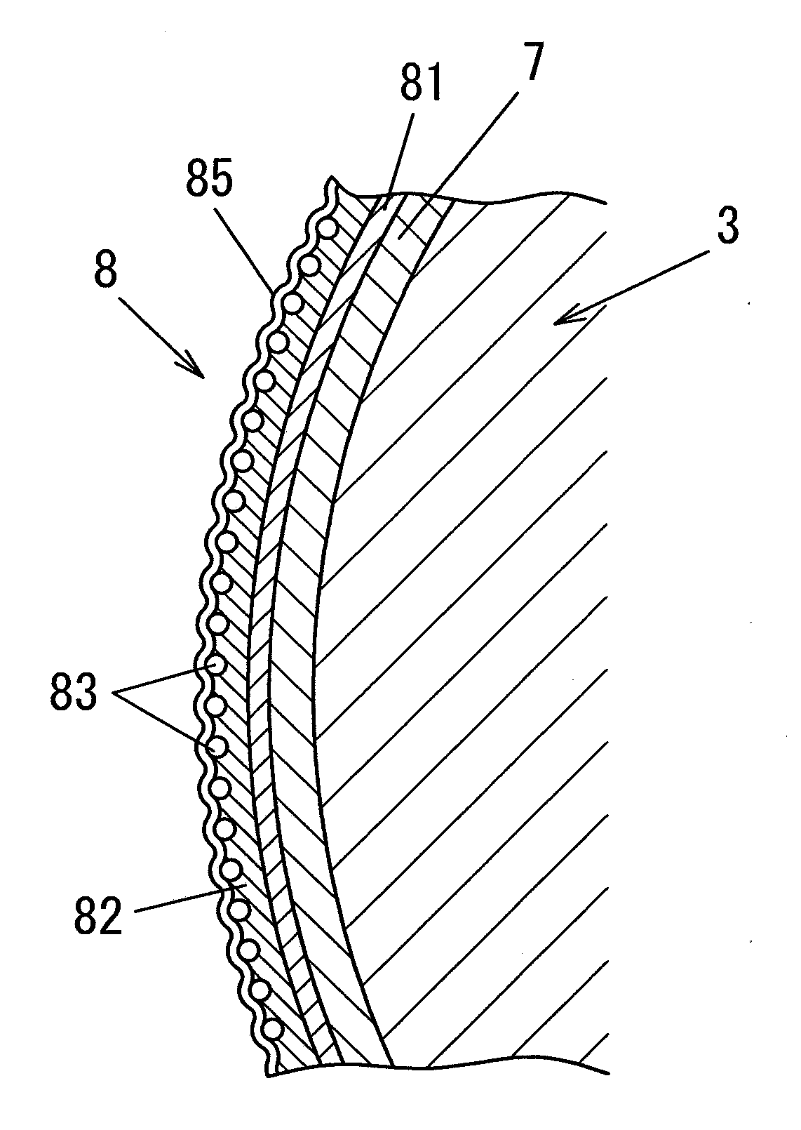
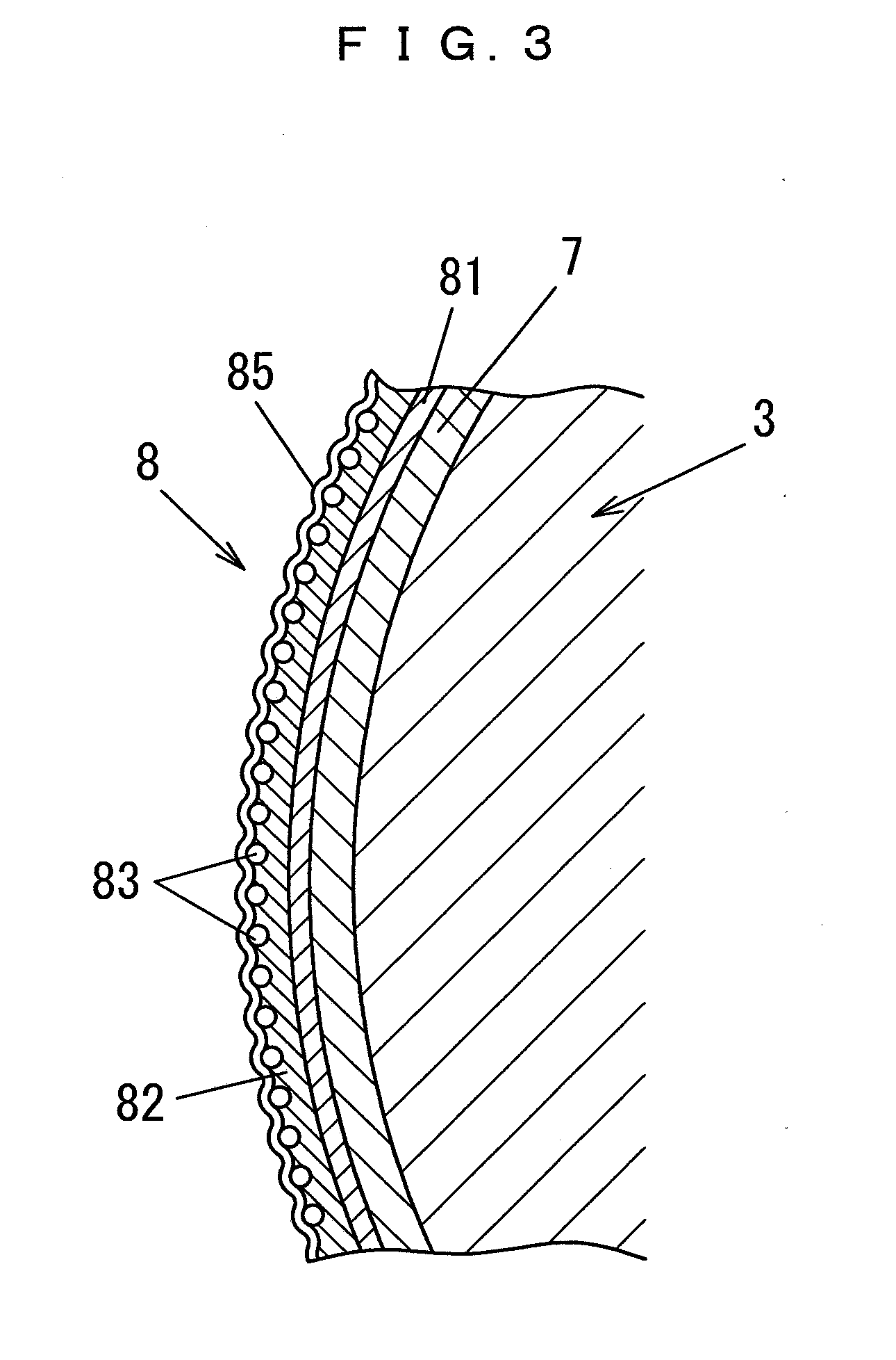
[0019]FIG. 3 is a partially enlarged cross-sectional view of a jacket according to the present invention which is wound around an impression cylinder 3, and shows the jacket comprising a two-layer structure comprising a flexible metal thin plate 7 having a thickness of 0.10 to 0.30 mm and a flexible ink smear preventive sheet 8. The ink smear preventive sheet 8 comprises an ink smear preventive structure provided on the surface of a flexible sheet substrate 81 made of a resin. An example of this ink smear preventive structure includes an adhesive layer 82 provided on the sheet substrate 81, with small balls 83 being partially embedded in the adhesive layer 82, and a cured resin layer 85 being formed of a low surface-energy resin on the exposed convex portions of these small balls 83, this surface layer (the cured resin layer 85) having a convex-concave surface (with su...


PUM

PropertyMeasurementUnit
surface roughnessaaaaaaaaaa
thicknessaaaaaaaaaa
total thicknessaaaaaaaaaa

Abstract

A composite structure for application to an impression cylinder or a transfer cylinder includes an ink smear preventing sheet having flexibility as a whole backed by a flexible metal thin plate. The work surface of the ink smear preventing sheet has an ink smear preventing structure in the form of a concave-convex configuration. The ink smear preventing sheet is of a flexible sheet of resin having an adhesive layer thereon in which are partially embedded many small balls to form the concave-convex structure.

Description

BACKGROUND OF THE INVENTION[0001]Generally, as an impression cylinder of an offset printing press, there is used a cylinder made of metal, having the surface finished with chrome plating. In offset printing, as is shown in FIG. 1, ink is transferred from a plate cylinder 1 to a blanket cylinder 2 and, thereafter, is pressed and transferred onto one surface of a printing substrate 4, fed between the blanket cylinder 2 and an impression cylinder 3, to form an ink image 5. Subsequently, when printing is to be performed on the reverse surface of the printing substrate (printing on both sides), the printing substrate 4 is printed in the next process on the reverse surface by feeding the substrate in an inverted state between a blanket cylinder 2 and the impression cylinder 3 which are constituted in the same way as above. In this process, as shown in FIG. 2, the ink image 5 which was printed first is transferred onto the impression cylinder 3 as a transferred ink image 6 and, then, this ...

Claims


Application Information

Patent Timeline
Patent Type & Authority Applications(United States)
IPC IPC(8): B41F13/18B21K1/02
CPCY10T29/49544B41F22/00
Inventor NISHIKAWA, YOSHIKIMISAWA, KENICHI
Owner SHINODA
Why Eureka
Try Eureka