Rare Earth Composite Magnets with Increased Resistivity

a composite magnet and resistivity technology, applied in the field of rare earth permanent magnets, can solve the problems of reducing the efficiency of rotary equipment, electrical resistivity, magnetic properties, etc., and achieve the effect of increasing the electrical resistivity of permanent magnets and reducing the loss of eddy current for motors and generators

Inactive Publication Date: 2011-03-10
ELECTRON ENERGY CORP +1
View PDF7 Cites 72 Cited by
  • Summary
  • Abstract
  • Description
  • Claims
  • Application Information

AI Technical Summary

Benefits of technology

[0006]An object of the invention is to increase electrical resistivity of per

Problems solved by technology

When the magnets are subjected to variable magnetic flux, if the electrical resistivity is low, a large amount of heat due to eddy current is generated, which in turn reduces their magnetic properties and therefore the eff

Method used


Image

  • Rare Earth Composite Magnets with Increased Resistivity
  • Rare Earth Composite Magnets with Increased Resistivity
  • Rare Earth Composite Magnets with Increased Resistivity

Examples


examples 1-6

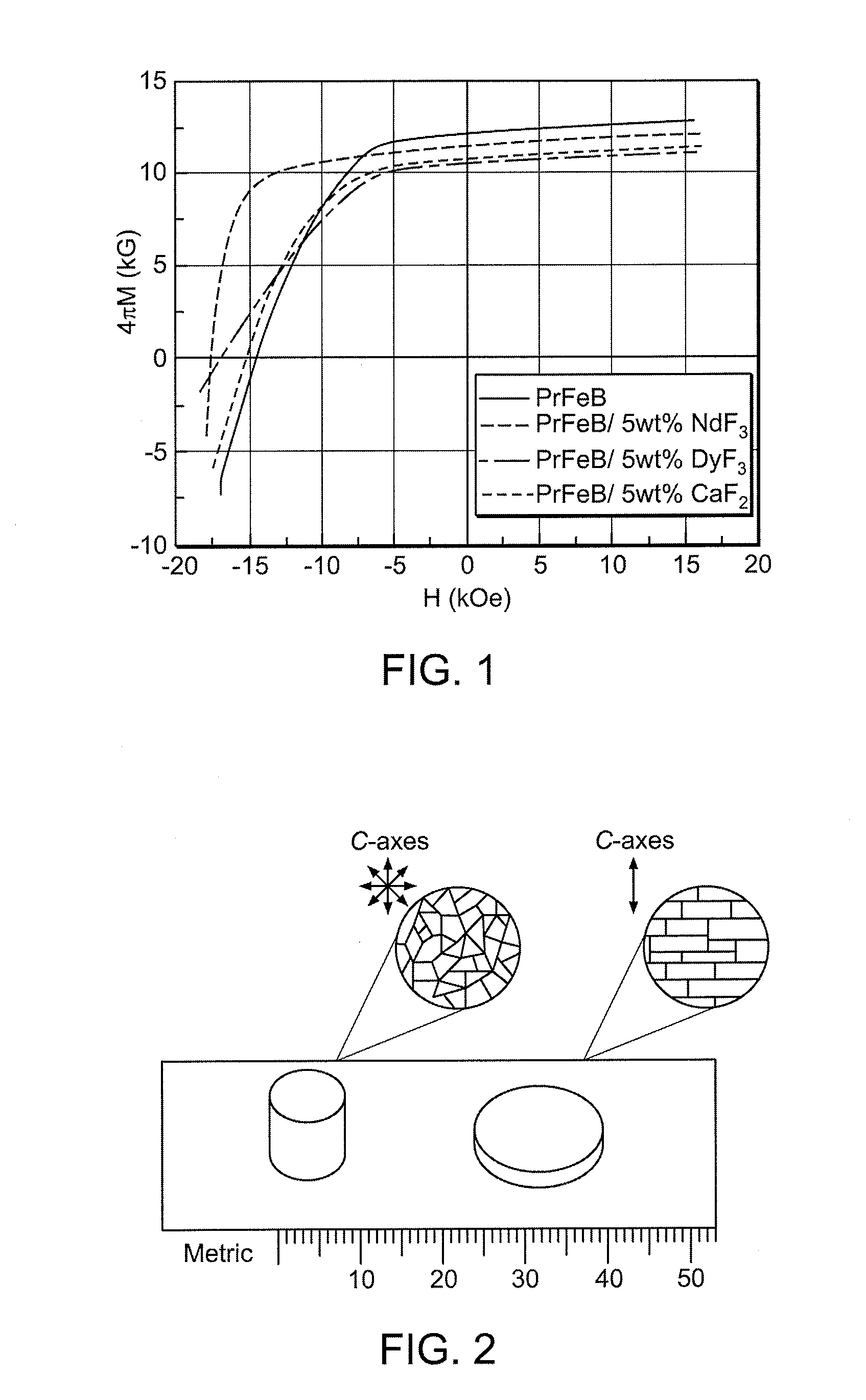
[0066]Development of Fe2F14B / fluoride magnets with increased electrical resistivity, Nd14.5Fe79.5B6, and Pr14.5Fe79.5B6 anisotropic permanent magnets were synthesized by hot pressing and die upsetting. The precursor powders were produced with a nanocrystalline structure by melt spinning 5% by wt. of NdF3 and DyF3 were added to the magnets. The magnets were hot pressed at 650-700° C. and die-upsetted (hot plastic deformation) at 800° C. The following results were observed:

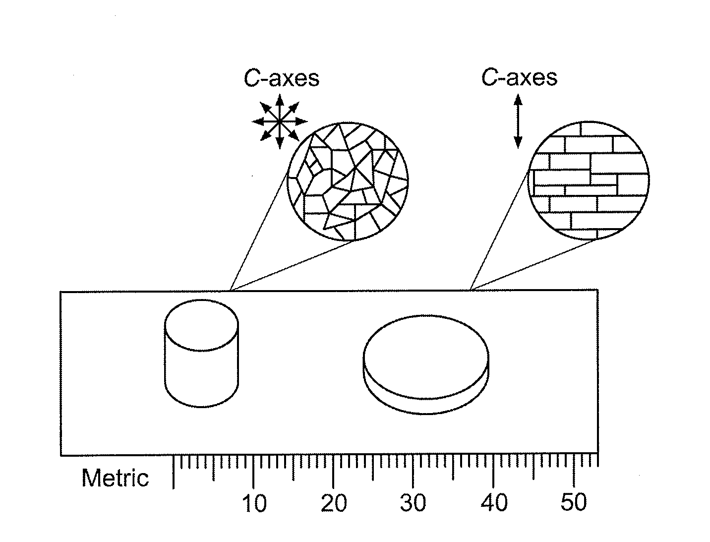
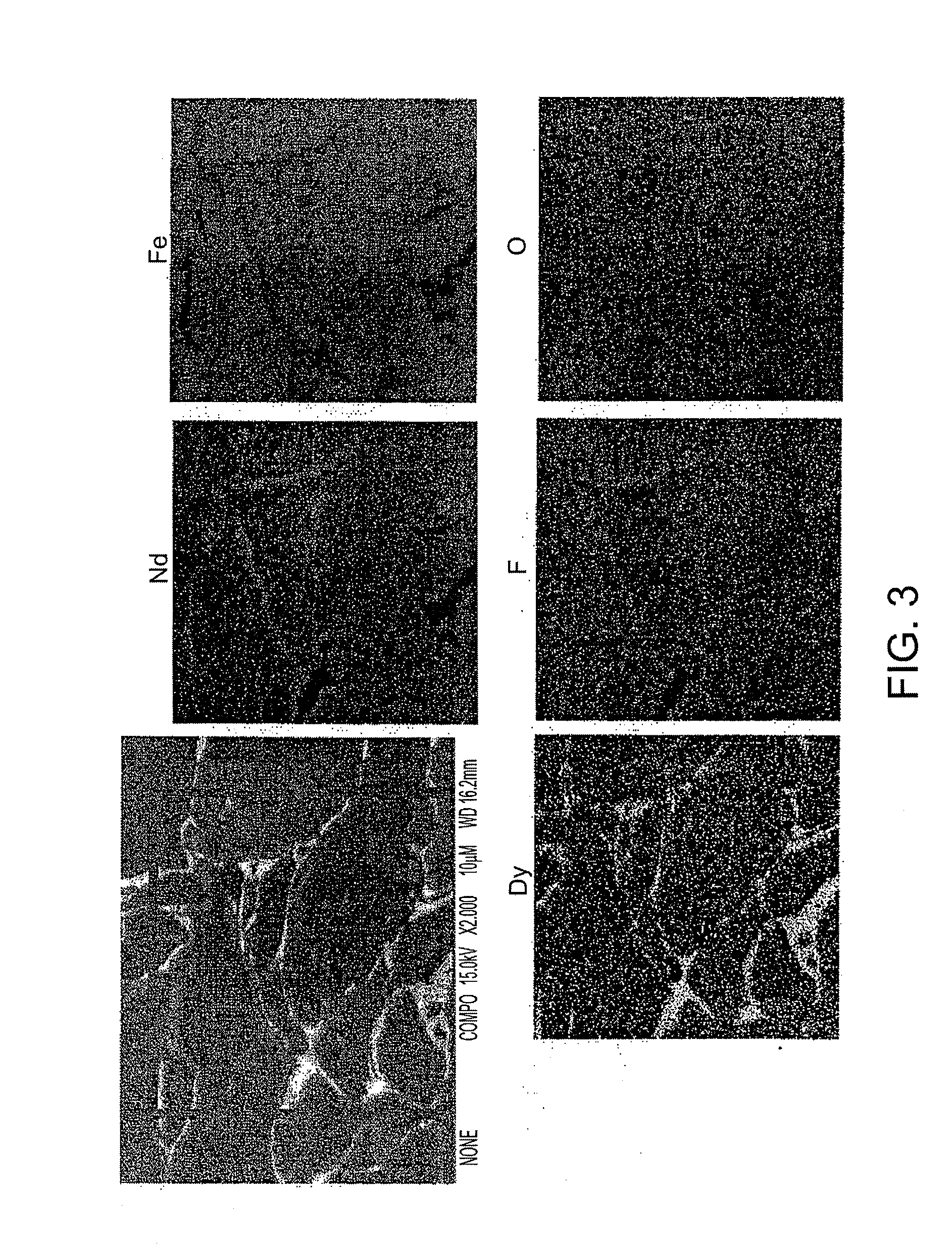
[0067]Almost fully dense composite (Pr, Nd)14.5Fe79.5B6 / NdF3 or DyF3 magnets produced by hot pressing and die upsetting show an electrical resistivity substantially higher than 2:14:1 magnets without fluoride, as summarized in Table 1. The great advantage of 2:14:1 phase in conjunction with rare earth fluorides is that upon hot pressing and die upsetting, the fluorides distribute in layers driven by a rare-earth rich phase which is in the molten state at the hot pressing and die upsetting temperature. Dy tends to co...


PUM

PropertyMeasurementUnit
Fractionaaaaaaaaaa
Microstructureaaaaaaaaaa
Electrical resistivityaaaaaaaaaa

Abstract

Dielectric rare earth fluorides are blended with rare earth magnet powders to produce high-resistivity fluoride composite rare earth magnets.

Description

STATEMENT OF GOVERNMENT SUPPORT[0001]This invention was made with government support under Grant No. DE-FG02-07ER86308 awarded by the Department of Energy. The United States government has certain rights in the invention.BACKGROUND OF THE INVENTION[0002]The present invention relates to rare earth permanent magnets for use in rotary equipment, motors and generators. Addressing eddy current losses represents one of the important factors in the design of motors and high speed generators. Reduction of these eddy current losses in permanent magnets used with rotary equipment is best achieved by increasing their electrical resistivity. When the magnets are subjected to variable magnetic flux, if the electrical resistivity is low, a large amount of heat due to eddy current is generated, which in turn reduces their magnetic properties and therefore the efficiency of rotary equipment. High resistivity is achieved by using various insulating means to increase the electrical resistivity of rar...

Claims


Application Information

Patent Timeline
IPC IPC(8): H01F7/02B22F3/12B22F1/105
CPCB22F1/007B22F2009/048H01F41/0293H01F1/059H01F1/0577H01F1/0572B22F2998/10C22C1/04C22C33/0207C22C33/0257C22C38/005C22C2202/02B22F3/105B22F3/15B22F3/17B22F1/105H01F1/0556H01F1/0557H01F1/0576H01F41/0266
Inventor MARINESCU, MELANIALIU, JINFANGGABAY, ALEKSANDRHADJIPANAYIS, GEORGE C.
Owner ELECTRON ENERGY CORP
Why Eureka
Try Eureka