Video display system

a video display and video technology, applied in the direction of identification means, electrical apparatus casings/cabinets/drawers, instruments, etc., can solve the problems of inability to use the exposed screen outdoors, easy vandalism and theft of exposed video units, etc., and achieve the effect of high degree of flexibility

Active Publication Date: 2011-03-10
COMARK LLC
View PDF42 Cites 153 Cited by
  • Summary
  • Abstract
  • Description
  • Claims
  • Application Information

AI Technical Summary

Benefits of technology

[0005]There is a need for a free-standing display system such as a kiosk, which may be placed in a variety of locations such as public plazas, sidewalks and the like. Such a system offers a high degree of flexibility for marketers and is desirable for modern marketing techniques.

Problems solved by technology

However, apart from certain closely monitored environments such as airports and retail stores, exposed video units can be exposed to vandalism and theft.
As well, outdoor use of an exposed screen is usually difficult as a result of exposure to moisture and extreme temperature conditions.
Conventional LCD monitors are suitable for operation in a temperature range of approximately 5° C. to 40° C. At temperatures above this range, the screen may not function and may be temporarily or permanently damaged, while below this range the display may also not function properly.
This presents a drawback for outdoor usage of LCD displays (and other flat panel digital monitors) that are enclosed within a housing, since temperatures can exceed this range.

Method used


Image

  • Video display system
  • Video display system
  • Video display system

Examples


first embodiment

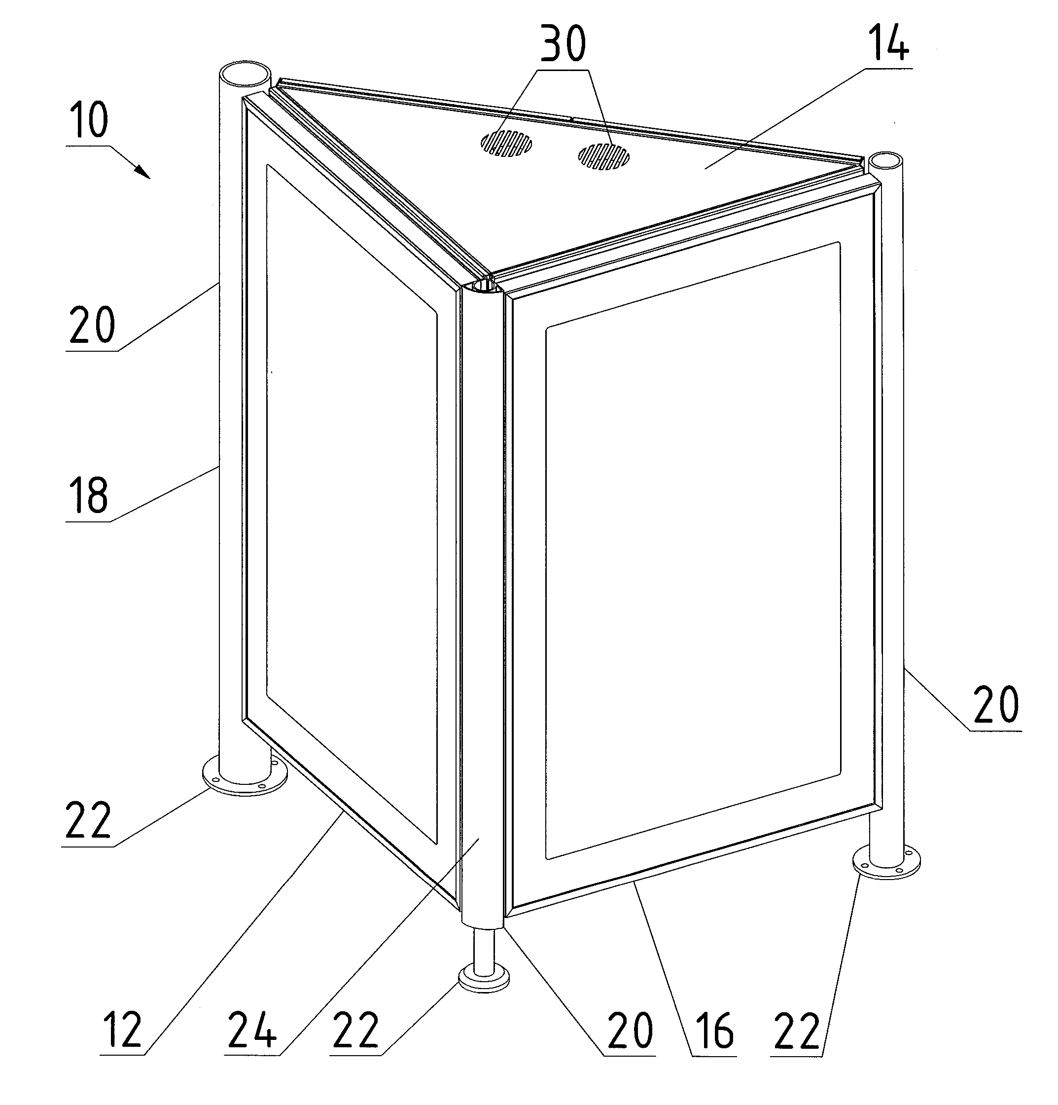
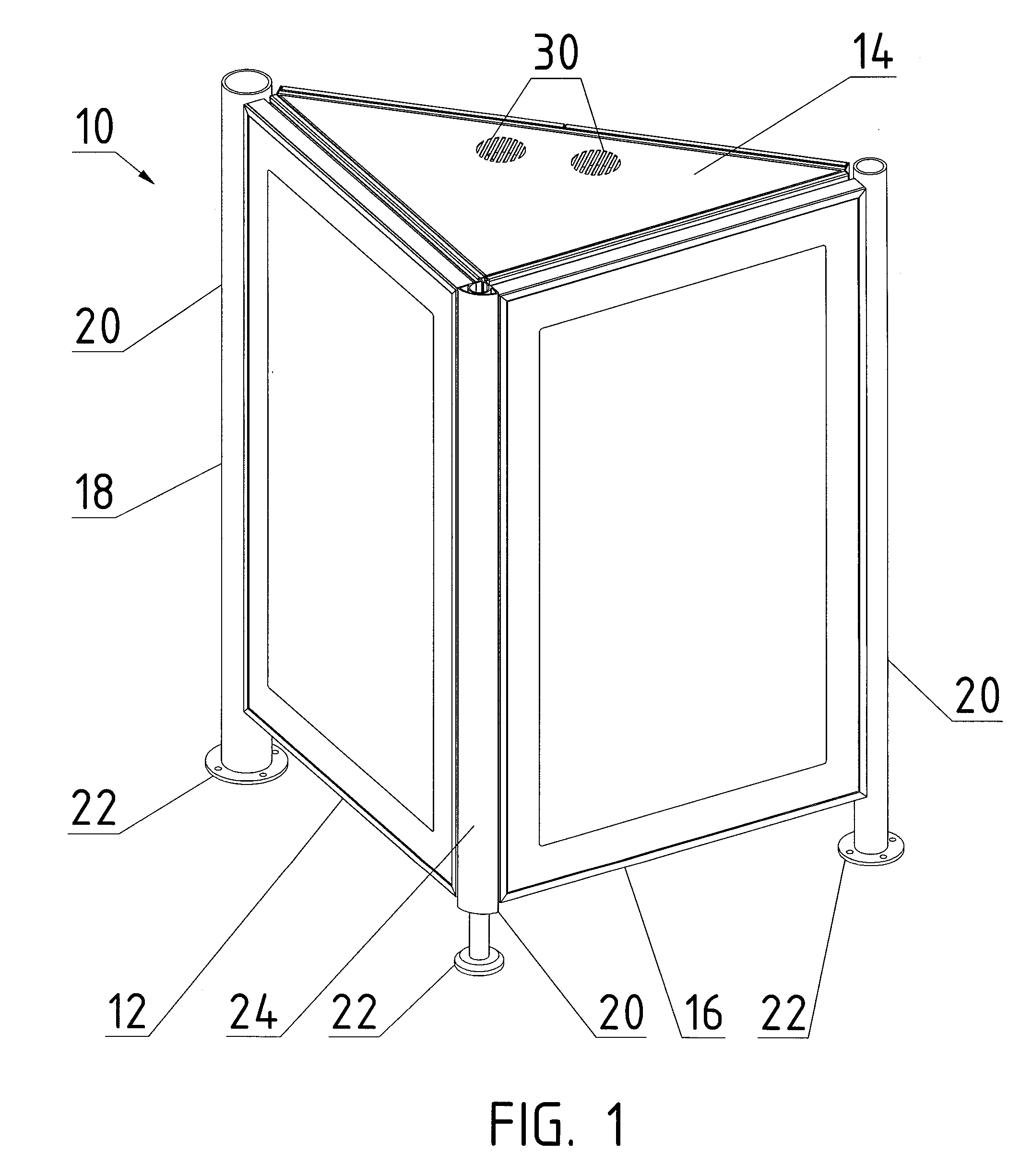
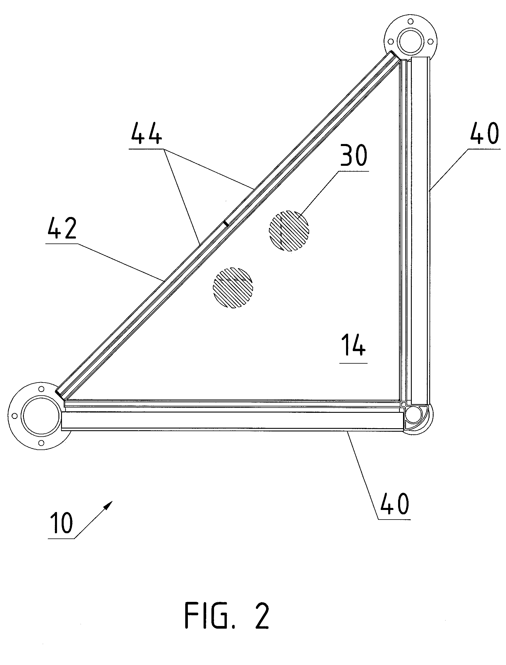
[0039]In a first embodiment, shown in FIGS. 1-8, the system comprises a free-standing display structure 10 having a substantially triangular cross-sectional configuration, with generally vertical rectangular sides. Structure 10 includes a rigid support frame 18, composed of three upright corner posts 20, each of which terminates in a foot 22. Feet 22 may be bolted to a substrate to minimize the risk of theft or movement. One or more of posts 20 are adjustable in length. Preferably, posts 20 are partly or fully covered with a decorative covering, such as powder coated sheet metal or a stainless steel tube 24. Posts 20 are connected together with cross bars 26, seen in FIG. 3. Triangular floor and roof panels 14 and 16 cover the upper and lower open ends of the module, and are mounted to cross bars 26. The floor and roof panels include ventilation openings 30, to permit ventilation of the assembly by convection. Optionally, ventilation fans 32 may be provided to vent the interior of t...

second embodiment

[0063] shown in FIG. 9, one or more enclosures 40 can be incorporated within a transit shelter 102. In this aspect, posts 20 may provide structural support for the shelter, thus integrating the video display with the shelter. The video system thus provides both structural support and shelter from the elements, in addition to the video display.

[0064]FIG. 10 illustrates a third embodiment consisting of a single or double-sided floor-standing (street-level) display 104 composed of either a single enclosure 40, or dual enclosures 40 arranged back-to-back. FIG. 11 illustrates a fourth embodiment, consisting of a one-sided, wall-mounted display 106. FIG. 12 illustrates a fifth embodiment, consisting of a two-sided, ceiling mounted display 108. The preceding systems of FIGS. 10-12 comprise one or two enclosures 40 as generally described above, wherein the enclosures are mounted within a frame 110 which supports the enclosure(s) in a suitable configuration.

sixth embodiment

[0065]A sixth embodiment is shown in FIGS. 13-22. In this version, enclosure 40 is adapted for maintaining a suitable operating temperature within its interior without the need for active cooling by an air conditioner or other heat exchanger, by generating a flow of ambient air through the enclosure. The enclosure consists of front and rear housings 200 and 210 which open like a clamshell, connected together with a removable hinged connection means, described below in more detail. Rear housing 210 encloses the FPD 100 and the ventilation components described herein, and front housing 200 includes the clear viewing panel 50. A pliable gasket where housings 200 and 210 meet provides a watertight seal.

[0066]The hinged connection means between the housings 200 and 210 is disposed horizontally along their respective upper edges to permit the front housing to swing away from the rear housing. The connection consists of opposed mutually engaging flanges 212 and 214. A first flange 212 exte...


PUM


Abstract

A video screen enclosure is disclosed for housing a flat panel video display unit (“FPD”), comprising a housing and a front panel member joined to the housing with an airtight seal. An environmental control unit (“ECU”) within housing includes means to internally circulate air within said enclosure to maintain a temperature within a range suitable for operation of said display, and a control system to maintain the interior temperature within said enclosure within a selected range suitable for operation of said FPD. The enclosure may form a sealed unit with interior air being recirculated through said ECU, or ambient air may be circulated through the enclosure.

Description

FIELD OF THE INVENTION[0001]The present invention relates to video display systems for use in public spaces, and in particular to an enclosure for holding a flat panel video display, environmental control systems for controlling the interior environment of such enclosures, and display structures incorporating such enclosures.BACKGROUND OF THE INVENTION[0002]Advertising and marketing displays often consist of non-static images, such as video images and other digital displays. For example, large-scale digital displays are widely used in major urban centers, as well as in stadiums, arenas, exterior walls of buildings and other applications. There exists an increasing need for smaller scale displays that are capable of displaying a static or dynamic video image so as to better attract the attention of onlookers. Displays of this nature may be used for advertising, public service information, and the like. As used in this patent specification, the terms “video display” or “flat panel dis...

Claims


Application Information

Patent Timeline
Patent Type & Authority Applications(United States)
IPC IPC(8): G06F1/16
CPCG09F9/30H05K7/20972G09F9/35
Inventor IDEMS, RALPHBOLTON, CHRISTOPHER JOHNYAN, GEORGE
Owner COMARK LLC
Why Eureka
Try Eureka