
Direct evaporator apparatus and energy recovery system

a technology of evaporator and energy recovery system, which is applied in the direction of lighting and heating apparatus, machines/engines, and greenhouse gas reduction. it can solve the problems of large amounts of recoverable waste heat, hydrocarbon working fluid useful, and working fluid subject to high temperature degradation

Inactive Publication Date: 2011-03-17
GENERAL ELECTRIC CO
View PDF9 Cites 27 Cited by
  • Summary
  • Abstract
  • Description
  • Claims
  • Application Information

AI Technical Summary

Problems solved by technology

Industrial turbomachinery such as turbines frequently create large amounts of recoverable waste heat in the form of hot gaseous exhaust streams.
As such, the working fluid is subject to degradation at high temperature.
Worse yet, a hydrocarbon working fluid useful in an organic Rankine cycle energy recovery system may begin degrade at temperatures far lower than 500° C. Thus, the use of an organic Rankine cycle energy recovery system to recover waste heat from a gas turbine system is faced with the dilemma that the temperature of the exhaust is too high to bring into direct thermal contact with the working fluid of the organic Rankine cycle energy recovery system.
However, the intermediate thermal fluid system can represent significant portion of the total cost of an organic Rankine cycle energy recovery system.
Furthermore, the intermediate thermal fluid system both increases the complexity of the organic Rankine cycle energy recovery system and represents an additional component the presence of which lowers the overall efficiency of thermal energy recovery.

Method used


Image

  • Direct evaporator apparatus and energy recovery system
  • Direct evaporator apparatus and energy recovery system
  • Direct evaporator apparatus and energy recovery system

Examples


Embodiment Construction

[0015]In the following specification and the claims, which follow, reference will be made to a number of terms, which shall be defined to have the following meanings.

[0016]The singular forms “a”, “an” and “the” include plural referents unless the context clearly dictates otherwise.

[0017]“Optional” or “optionally” means that the subsequently described event or circumstance may or may not occur, and that the description includes instances where the event occurs and instances where it does not.

[0018]It is also understood that terms such as “top,”“bottom,”“outward,”“inward,” and the like are words of convenience and are not to be construed as limiting terms. Furthermore, whenever a particular feature of the invention is said to comprise or consist of at least one of a number of elements of a group and combinations thereof, it is understood that the feature may comprise or consist of any of the elements of the group, either individually or in combination with any of the other elements of...


PUM


Abstract

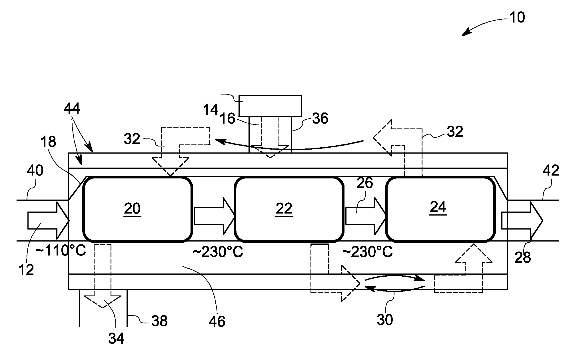
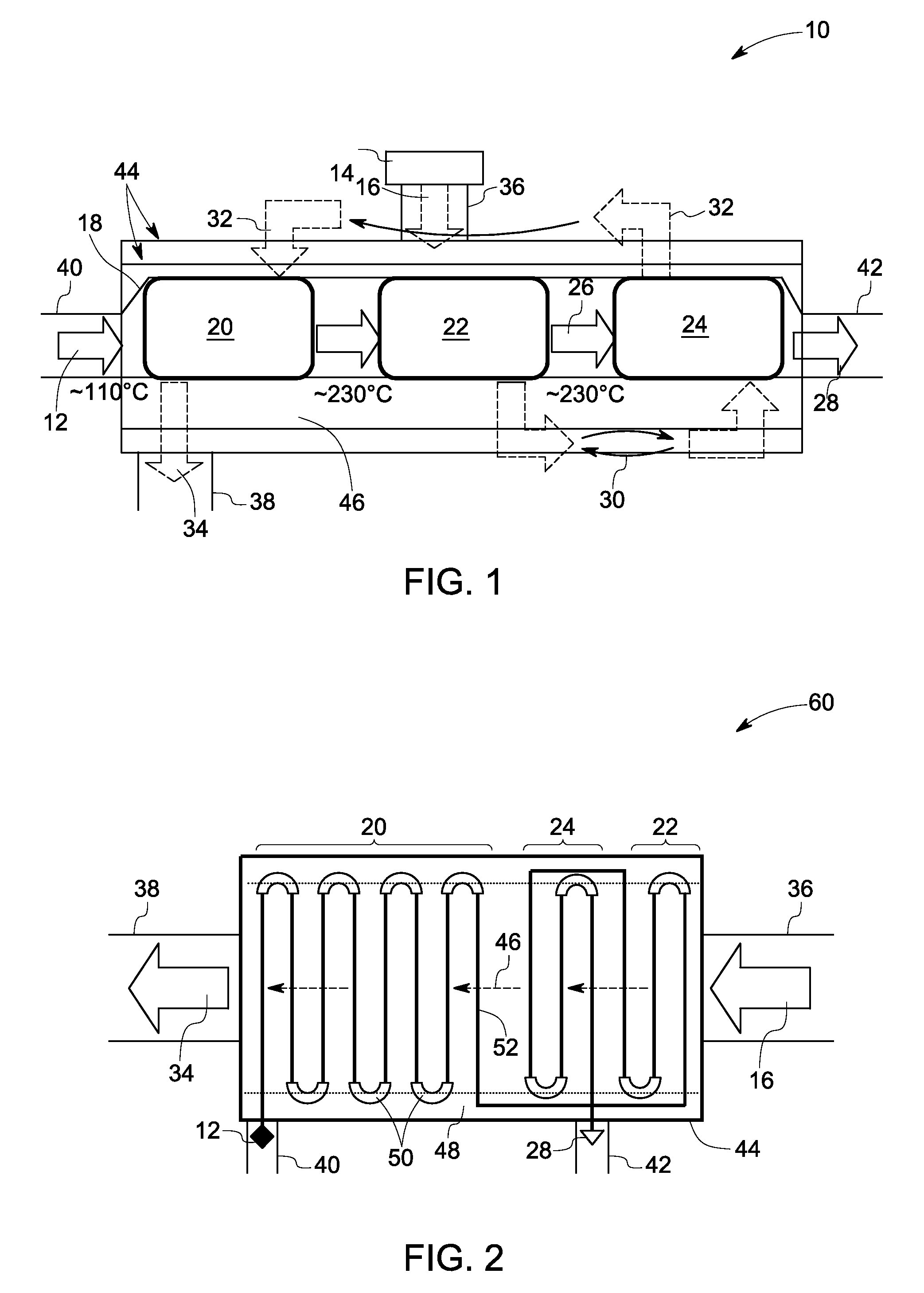
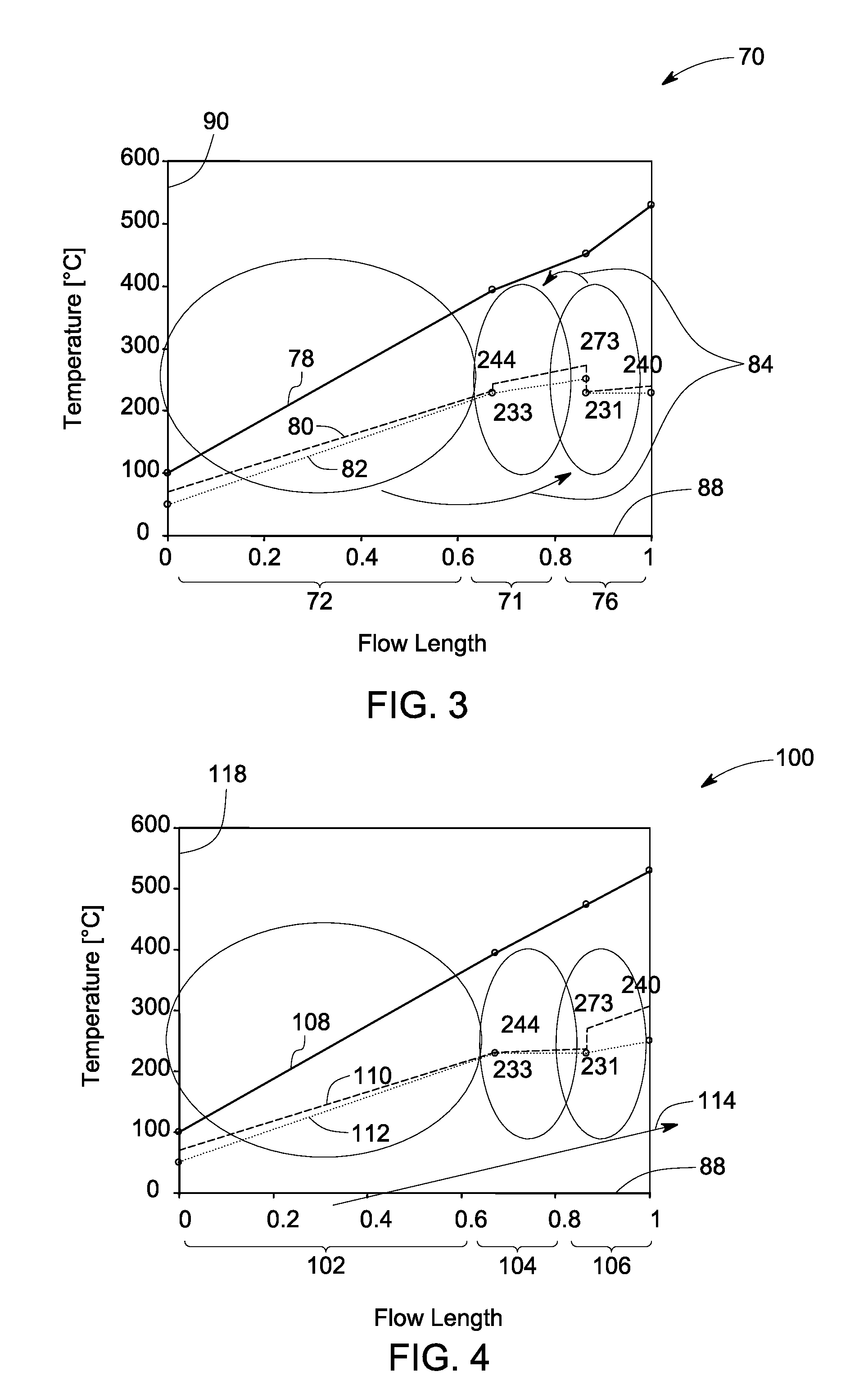
In one aspect of the present invention provides a direct evaporator apparatus for use in an organic Rankine cycle energy recovery system, comprising: (a) a housing comprising a heat source gas inlet, and a heat source gas outlet, said housing defining a heat source gas flow path from said inlet to said outlet; and (b) a heat exchange tube disposed entirely within said heat source flow path, said heat exchange tube being configured to accommodate an organic Rankine cycle working fluid, said heat exchange tube comprising a working fluid inlet and a working fluid outlet, said heat exchange tube defining three zones, a first zone adjacent to said heat source gas outlet, a second zone adjacent to said heat source gas inlet, and a third zone disposed between said first zone and said second zone, said working fluid inlet being in direct fluid communication with said first zone, and said working fluid outlet being in direct fluid communication with said third zone; wherein said first zone is not in direct fluid communication with said third zone. An organic Rankine cycle energy recovery system and a method of energy recovery are also provided.

Description

BACKGROUND[0001]The invention relates generally to an organic Rankine cycle energy recovery system, and more particularly to a direct evaporator apparatus and method for energy recovery employing the same.[0002]So called “waste heat” generated by a large number of human activities represents a valuable and often underutilized resource. Sources of waste heat include hot combustion exhaust gases of various types including flue gas. Industrial turbomachinery such as turbines frequently create large amounts of recoverable waste heat in the form of hot gaseous exhaust streams.[0003]Organic Rankine cycle energy recovery systems have been deployed as retrofits for small- and medium-scale gas turbines, to capture waste heat from the turbine's hot gas stream and convert the heat recovered into desirable power output. In an organic Rankine cycle, heat is transmitted to an organic fluid, typically called the working fluid, in a closed loop. The working fluid is heated by thermal contact with t...

Claims


Application Information

Patent Timeline
IPC IPC(8): F01K7/34F01K25/00
CPCF01K23/10F01K25/10F22B1/1807Y02T10/16F28D21/001F01N5/02F28D7/1623Y02E20/30Y02T10/12
Inventor LEHAR, MATTHEW ALEXANDERFREUND, SEBASTIAN W.FREY, THOMAS JOHANNESAUMANN, RICHARDAST, GABOR
Owner GENERAL ELECTRIC CO
Learn More