Stage equipped with alignment function, processing apparatus having the stage equipped with alignment function, and method of aligning substrate

a technology of processing apparatus and stage, which is applied in the direction of electrical apparatus, manufacturing tools, conveyors, etc., can solve the problems of affecting the quality of the product, the size of the apparatus itself will necessarily have to be large, and the transfer table must also be moved, so as to achieve high accuracy and reduce the time of alignment , the effect of short tim

Inactive Publication Date: 2011-03-17
ULVAC INC
View PDF2 Cites 18 Cited by
  • Summary
  • Abstract
  • Description
  • Claims
  • Application Information

AI Technical Summary

Benefits of technology

[0015]In case the alignment in the θ direction is performed on the above-mentioned stage, not only is required the positioning accuracy (e.g., below 1μ radian), but also is strongly required the reduction in alignment time. In this case, preferably, the drive means comprises: a fine-adjustment mechanism for rotating the suction means within a predetermined micro-angle range; and a coarse-adjustment mechanism for rotating the suction means within an angle range larger than the angle range of the fine-adjustment mechanism. According to this arrangement, after driving the object to be processed, by the coarse-adjustment mechanism, at a high speed to the neighborhood of a target position, a high-precision positioning can thereafter be performed by the fine-adjustment mechanism. As a result, high-accuracy alignment can be materialized at a short time.
[0016]Preferably, the coarse-adjustment mechanism is coupled to the suction means. The fine-adjustment mechanism comprises an arm and a drive source for swinging the arm. The fine-adjustment mechanism and the coarse-adjustment mechanism are operatively coupled to each other such that, when the arm is swung by the drive source, the suction means is rotatably driven through the coarse-adjustment mechanism. Then, the rotary shaft to rotatably drive the suction means can be made in common with each other, thereby eliminating the complex structure of the drive means. In addition, at the time of performing alignment in the θ direction, switching can be made smoothly from the rotatable driving with the coarse-adjustment mechanism to the rotatable driving with the fine-adjustment mechanism.
[0017]Further, the arm of the fine-adjustment mechanism has a length to be extended at least to one side of the stage main body and is connected at a front end of the arm to the drive source. Then, the amount of displacement of the front end of the arm required for movement by a predetermined micro-angle range will become large. As a result, the resolution of the detection means such as an encoder to detect the amount of displacement can be improved to thereby materialize a higher precision alignment.

Problems solved by technology

As a result, the apparatus itself will necessarily have to be large in size.
In addition, in order to align the stage at a high accuracy by rotating the stage, there will be needed a motor which is of high thrust force and high-performance, thereby resulting in a disadvantage of a higher cost.
This idea has, however, a disadvantage in that the transfer table must also be moved in the X-axis direction and in the Y-axis direction depending on necessity while rotating the supporting means at the time of alignment in the θ direction.
The control to perform high-accuracy alignment will be remarkably complicated.

Method used


Image

  • Stage equipped with alignment function, processing apparatus having the stage equipped with alignment function, and method of aligning substrate
  • Stage equipped with alignment function, processing apparatus having the stage equipped with alignment function, and method of aligning substrate
  • Stage equipped with alignment function, processing apparatus having the stage equipped with alignment function, and method of aligning substrate

Examples


Embodiment Construction

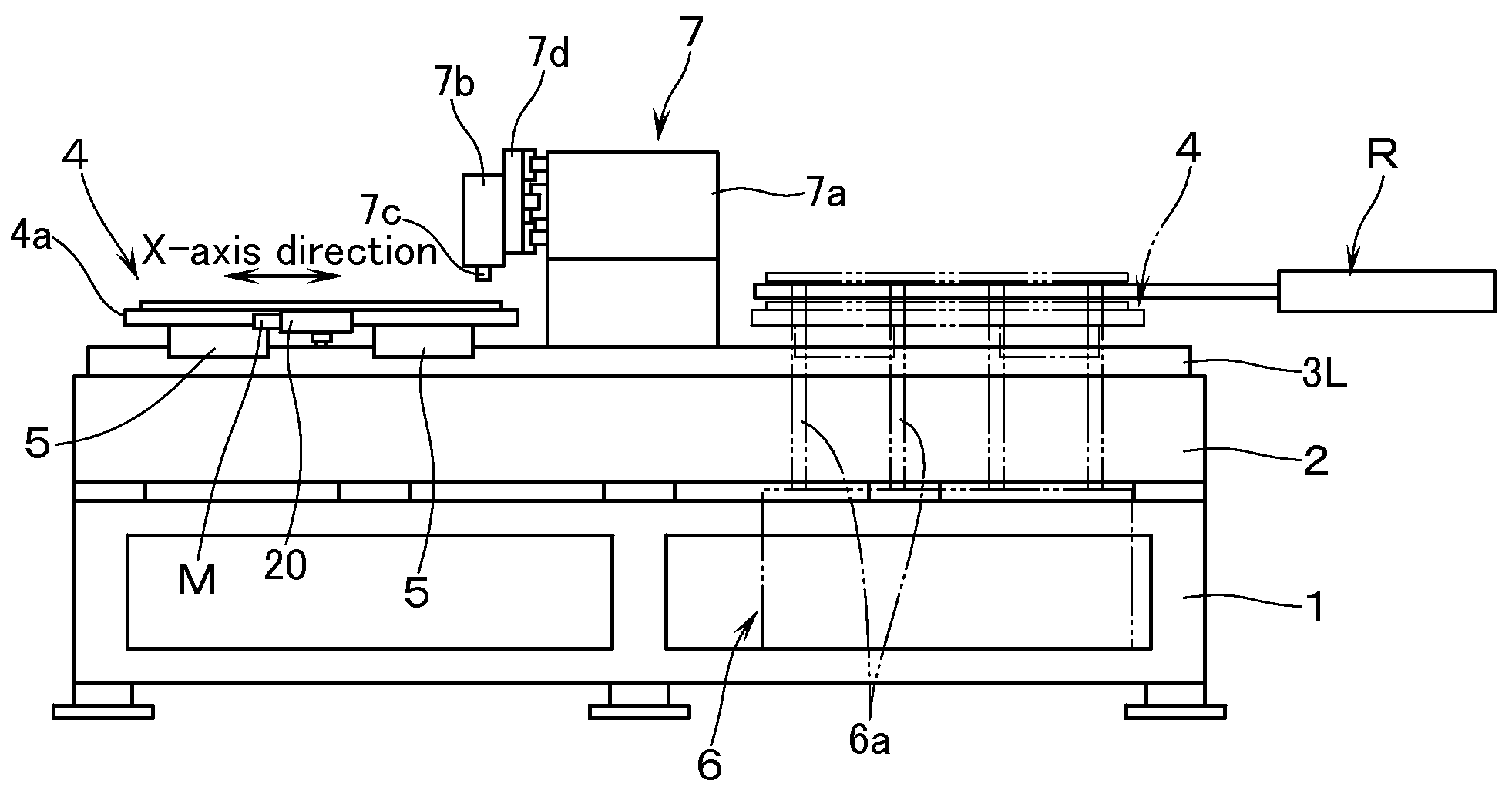
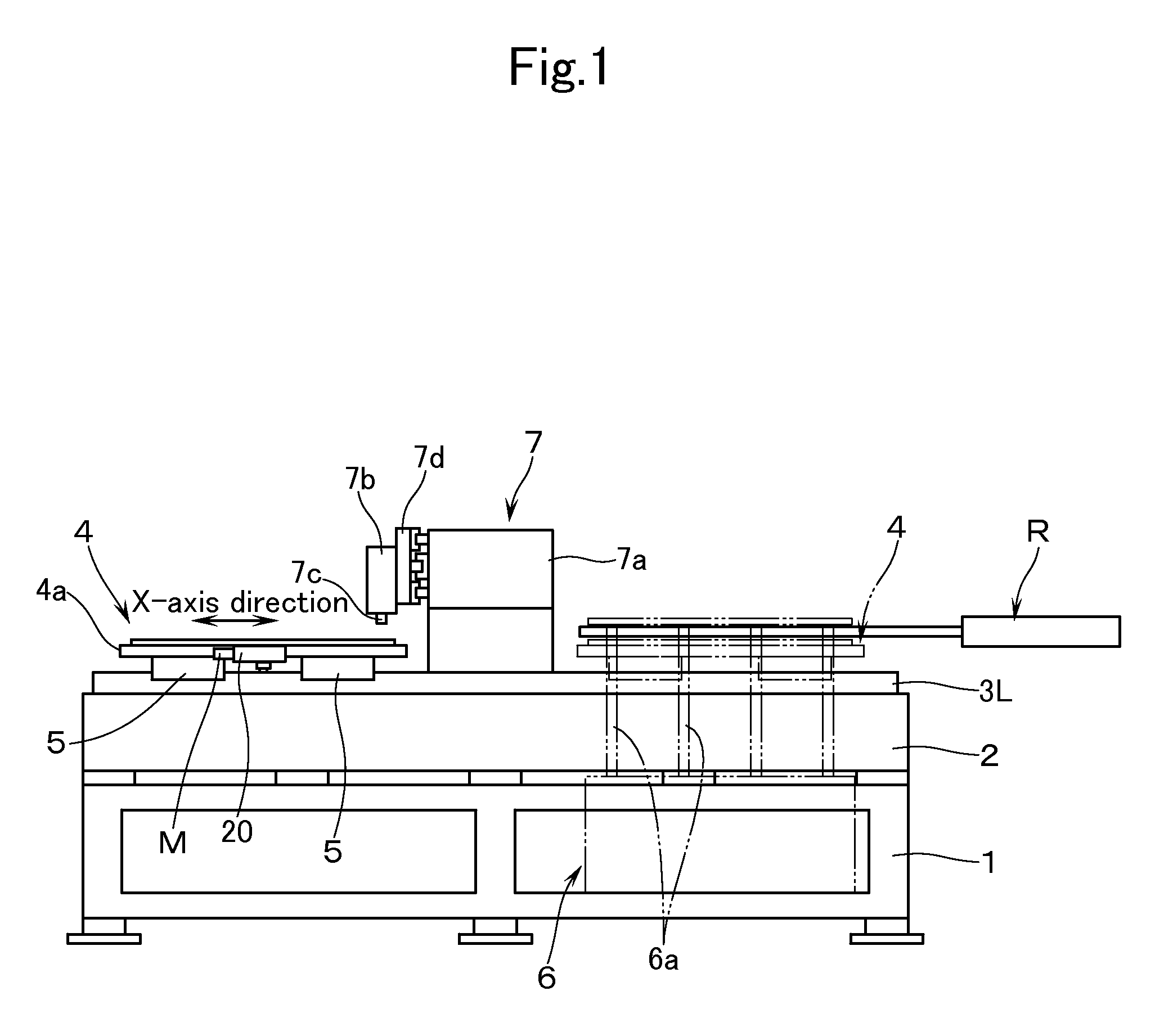
[0021]With reference to the drawings, description will now be made of an example in which a substrate S made of glass and the like for directly forming thereon electrically conductive fine patterns and the like is defined as an object to be processed, and in which a stage equipped with an alignment function and for holding the substrate S according to an embodiment of this invention is applied to an inkjet type of coating apparatus.

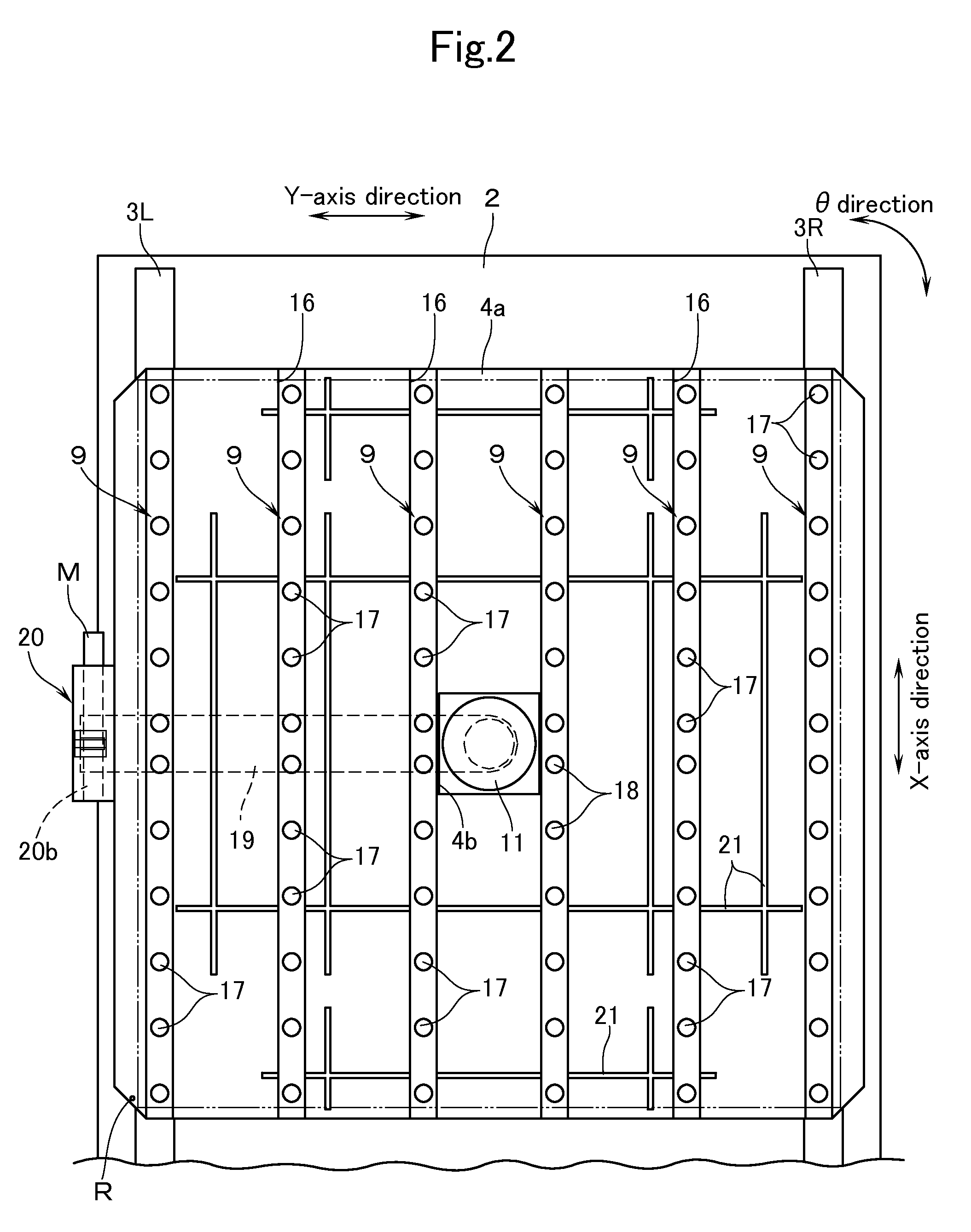
[0022]The inkjet apparatus has a platform 1, and on this platform 1 is disposed a base plate 2 which is rectangular parallelepiped in shape. The base plate 2 is made of granite and the like so as to secure smoothness on the top surface thereof. The top surface of the base plate 2 is provided with a pair of right and left rail members (guide means) 3R, 3L which are extended horizontally in the axial direction over the entire length of the base plate 2 (see FIG. 2).

[0023]On the rail members 3R, 3L, a stage 4 which is equipped with an alignment function is d...


PUM


Abstract

There is provided an inexpensive stage which is equipped with an alignment function and is capable of easily performing high-accuracy alignment especially in a θ direction even in case an object to be processed is large in weight. The stage equipped with an alignment function has a stage main body for holding a substrate while leaving a processing surface thereof open to access. The stage is provided with: a suction means capable of sucking that surface of the substrate which lies opposite to the processing surface; a gas supply means for supplying a gas to such a region of the substrate as is other than a portion sucked by the suction means; and a drive means to give a rotating force to the suction means so that the substrate can be rotated on the same plane by causing the suction means to serve as the center of rotation.

Description

TECHNICAL FIELD [0001]The present invention relates to a stage equipped with an alignment function, a processing apparatus having the stage equipped with an alignment function, and a method of aligning a substrate. The invention relates, in particular, to those which are used in an inkjet type of coating apparatus provided with coating heads which are disposed in a manner to be movable along an axis.BACKGROUND ART [0002]It is known to use an inkjet type of coating apparatus (hereinafter referred to as a “coating apparatus”) in order to directly form, on a substrate, electrically conductive fine patterns, and the like without going through a photolithography process. The apparatus is recently used in forming very fine source / drain electrode patterns of several μ mm in the step of manufacturing large-area thin film transistor substrates, and also in forming color filters, alignment layers and spacers for flat panel displays.[0003]As this kind of coating apparatus, there is known one, ...

Claims


Application Information

Patent Timeline
Patent Type & Authority Applications(United States)
IPC IPC(8): B25B11/00
CPCB65G49/061B65G49/065B65G49/067H01L21/68785H01L21/68H01L21/6838B65G2249/045
Inventor SATO, SEIICHIYAHAGI, MITSURUMINAMI, HIROFUMIMUSHA, KAZUHIROTAKAHASHI, MAKOTO
Owner ULVAC INC
Why Eureka
Try Eureka