Transmission-guard system and method for an inductive power supply

a technology of inductive power supply and transmission guard, which is applied in the direction of inductance, battery data exchange, exchanging data charger, etc., can solve the problems of dangerous hotness of uncoupled high-power primary coil or its surroundings, and the energy loss of high-power inductive transfer systems is typically larger than the average,

Active Publication Date: 2011-03-17
POWERMAT TECHNOLOGIES
View PDF100 Cites 218 Cited by
  • Summary
  • Abstract
  • Description
  • Claims
  • Application Information

AI Technical Summary

Benefits of technology

[0027]It is a further aim of the invention to present a transmission-guard for preventing an inductive power outlet from transmitting power in the absence of an electric load inductively coupled thereto, the inductive power outlet comprising at least one primary coil conn

Problems solved by technology

It will be appreciated however, that base units such as Hui's charging surface which transmit energy continuously, in a largely uniform manner over an extended area, are not suitable for use with high energy systems, such as those required to power computers, light bulbs, televisions and the like.
Energy losses associated with high power inductive transfer systems are typically larger than those in low power systems such as Hui's charging surface.
In addition whereas in low power systems excess heat may be readily di

Method used


Image

  • Transmission-guard system and method for an inductive power supply
  • Transmission-guard system and method for an inductive power supply
  • Transmission-guard system and method for an inductive power supply

Examples


Embodiment Construction

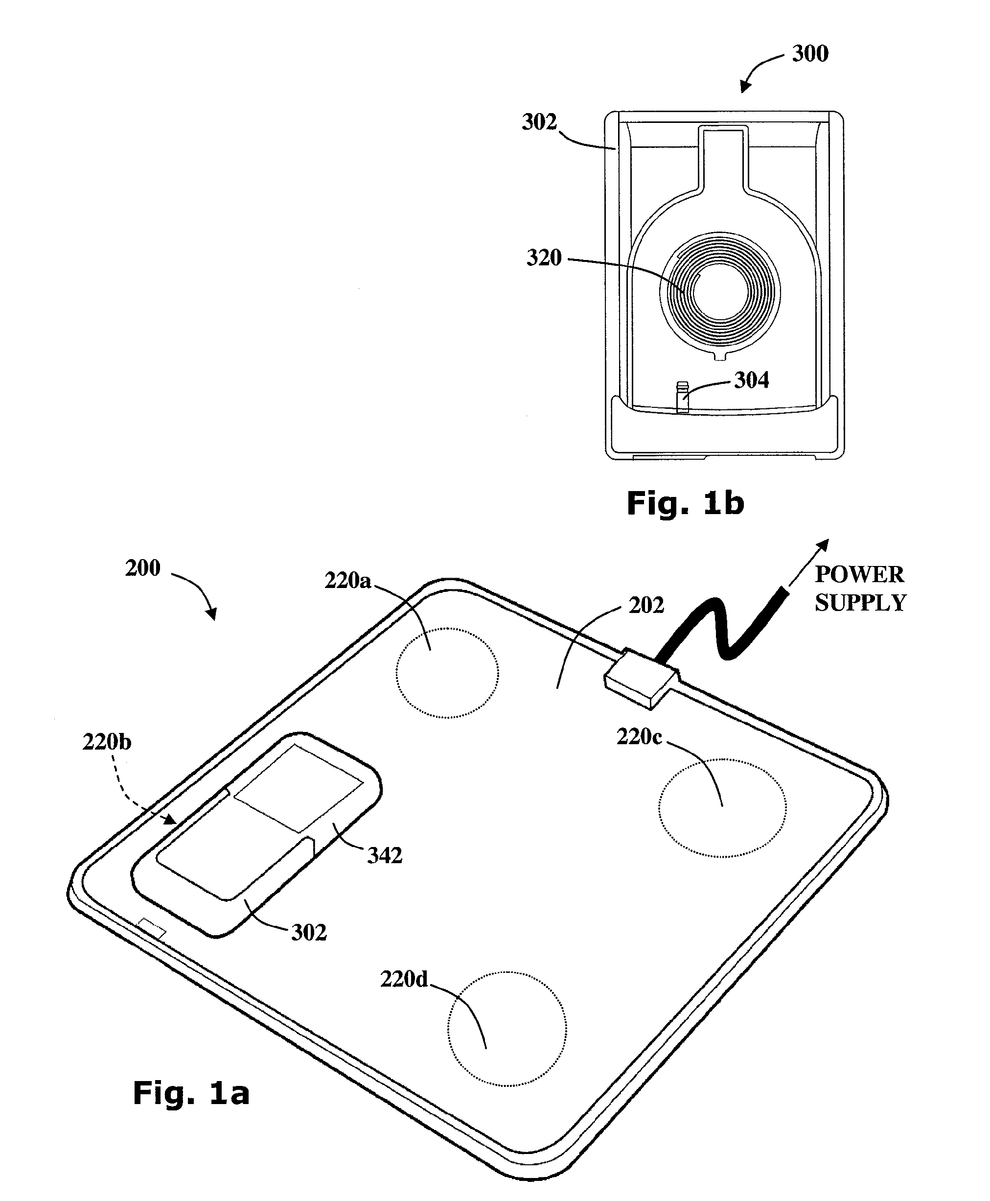
[0071]Reference is now made to FIGS. 1a and 1b showing an inductive power outlet 200 and an inductive power receiver 300 for use in an exemplary inductive power transfer system 100 according to an exemplary embodiment of the invention.

[0072]The inductive power outlet 200 consists of four primary inductors 220a-d incorporated within a platform 202. The inductive power receiver 300 includes a secondary inductor 320 incorporated within a case 302 for accommodating a mobile telephone 342. When a mobile telephone 342 is placed within the case 302 a power connector 304 electrically connects the secondary inductor 320 with the mobile telephone 342. As shown in FIG. 1a, the inductive power receiver 300 may be placed upon the platform 202 in alignment with one of the primary inductors 220b so that the secondary inductor 320 inductively couples with the primary inductor 220b.

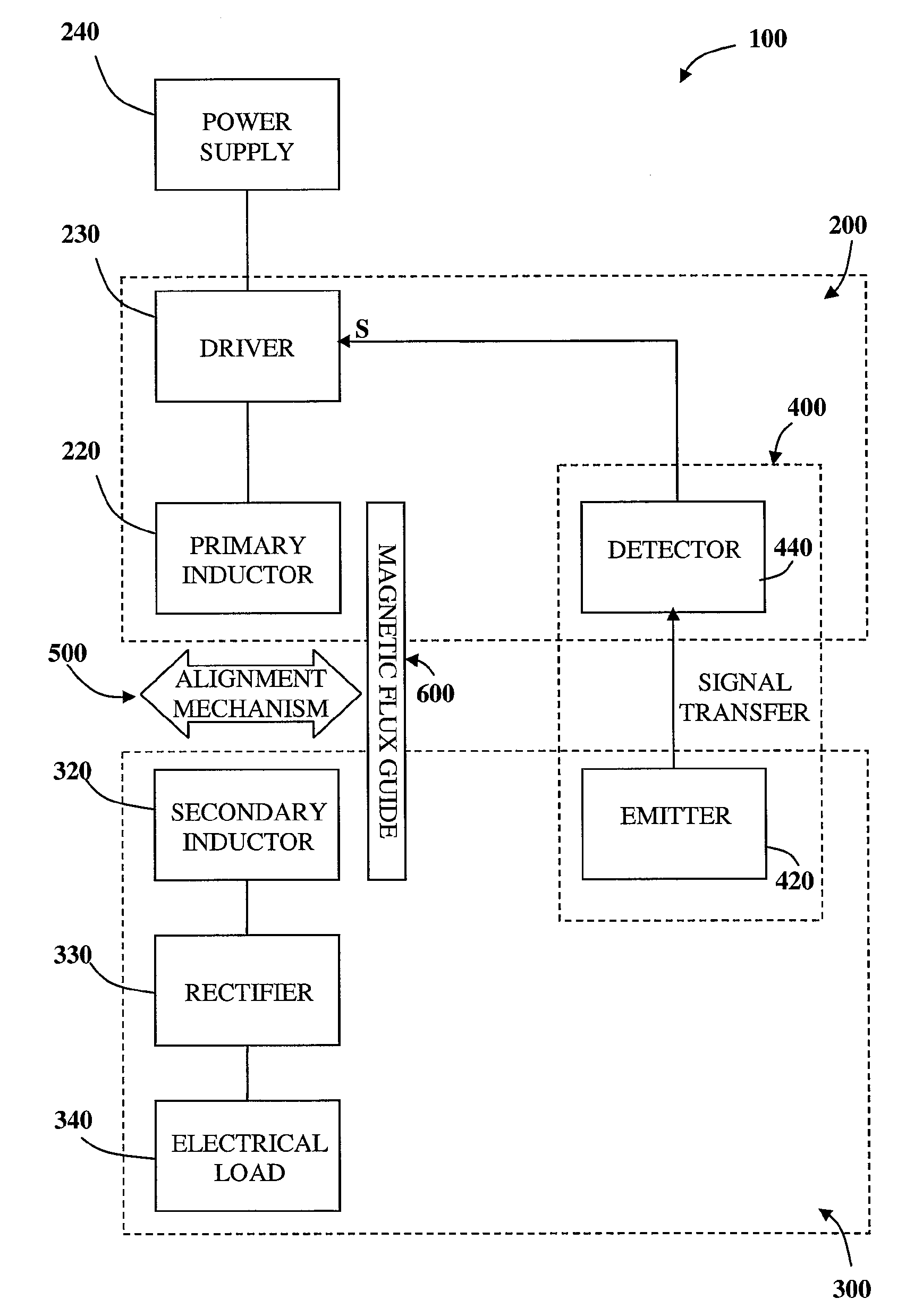
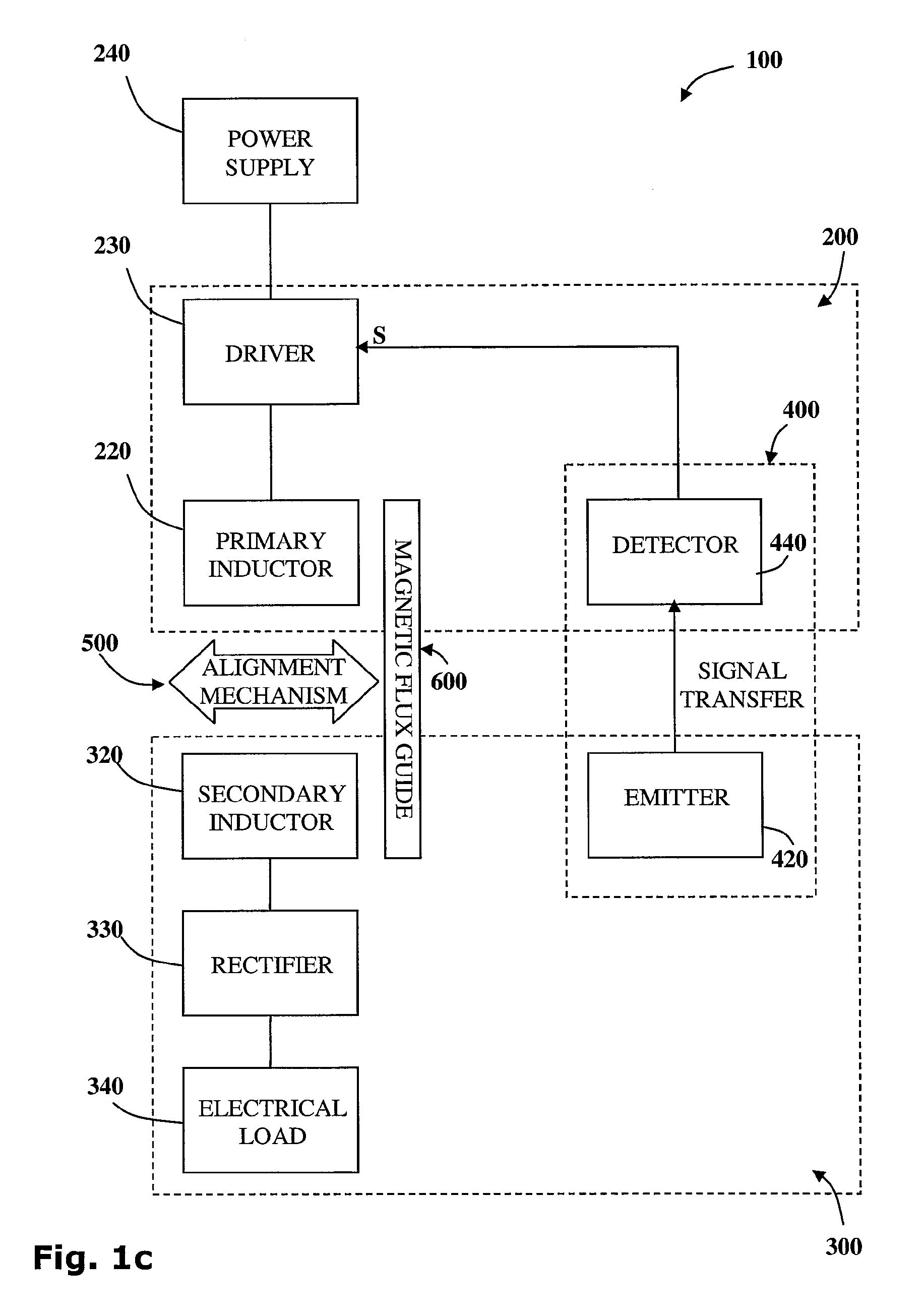
[0073]Referring now to FIG. 1c, which shows a block diagram representing the main components of the inductive transfer...


PUM


Abstract

A transmission-guard is disclosed for preventing an inductive power outlet from transmitting power in the absence of an inductive power receiver. A transmission lock is associated with an inductive power outlet and a transmission key is associated with an inductive power receiver. The transmission lock is configured to prevent a primary inductor from connecting to the power supply unless triggered by a release signal via the transmission key.

Description

CROSS REFERENCE TO RELATED APPLICATION[0001]This application is a continuation of PCT application Serial No. PCT / IL2008 / 001641 filed Dec. 18, 2008, which claims the benefit of U.S. provisional application Ser. Nos. 61 / 064,618 filed Mar. 17, 2008, 61 / 071,151 filed Apr. 15, 2008, 61 / 129,526 filed Jul. 2, 2008, 61 / 129,859 filed Jul. 24, 2008 and 61 / 129,970 filed Aug. 4, 2008, which are hereby incorporated by reference in their entirety.FIELD OF THE INVENTION[0002]The present invention is directed to inductive electrical power transfer. More specifically, the present invention relates to providing a transmission guard for preventing an inductive power outlets from transmitting power in the absence of an inductive power receiver.BACKGROUND OF THE INVENTION[0003]Inductive power coupling, as known in the art, allows energy to be transferred from a power supply to an electric load without connecting wires. A power supply is wired to a primary coil and an oscillating electric potential is ap...

Claims


Application Information

Patent Timeline
IPC IPC(8): H01H83/00
CPCH01F27/266H01F27/365H02J17/00H01F2038/143H02J7/025H01F38/14H02J50/12H02J7/00034H02J50/70H01F27/36H01F27/366H02J50/402H02J7/0044H02J50/80H02J50/90
Inventor AZANCOT, YOSSIBEN-SHALOM, AMIRGREENWALD, OOLAROFE, ARIKLEI-BOVITZ, ALFREDRHODES, DOVMEYUHAS, NOAM
Owner POWERMAT TECHNOLOGIES
Why Eureka
Try Eureka