
Small diameter video camera heads and visualization probes and medical devices containing them

a technology of video camera and probe, which is applied in the field of small diameter video camera head and visualization probe and medical devices containing it, can solve the problems of not being able unable to reach certain locations in the body, and unable to advance one of the prior art instruments

Active Publication Date: 2011-03-17
SCOUTCAM LTD
View PDF27 Cites 108 Cited by
  • Summary
  • Abstract
  • Description
  • Claims
  • Application Information

AI Technical Summary

Benefits of technology

[0033]In embodiments of the video camera head of the invention the length of the objective lens assembly is 2.0 mm or less. In other embodiments the length of the objective lens assembly is 1.5 mm or less.
[0034]In embodiments of the video camera head of the invention in which the photosensitive elements of the solid state pick up

Problems solved by technology

As said, due to their size all the abovementioned instruments cannot reach certain locations in the body without causing a significant trauma to the patient.
Others might severely endanger the safety of the patient and due to their size might cause severe damages.
In an endoscopic brain surgery procedure performed through the nose, i.e., trans-nasal, it is not possible to advance one of the prior art instruments due to the dimension involved in creating a tunnel and the brain configuration.
Moreover, if an instrument greater than 2 mm is introduced without a good image and superb articulation, safety and trauma issues will block it before it reaches its destination.
The same problem applies to other organs as well, such as heart arteries, kidneys, common bile duct, pancreas, lungs, etc.
These cameras require superb electronics and state-of-the-art sensors, optics and image processing, as well as hand assembly of the camera head and optics, all of which results in very expensive equipment.
The resulting equipment has to be reused via sterilization because of cost considerations, which in turn entails handing costs.
This requirement dictates compromises when designing endoscopic devices, because, for example, large working channels, i.e. the pipes which enable other tools to enter the region of interest in the body through the endoscopic device without affecting the internal parts of the endoscopic device, will dictate the use of a small imager or minute cables for articulation, or minimum illumination, etc.
It is well known in the art that miniature imagers suffer from noisy images due to insufficient illumination caused by small diameter illumination fibers, VCSELs or LEDs employed.
Such a sensor will yield an endoscopic device with minimum Outer Diameter of 1.6 mm without any working channel but with a poor image in comparison to the CCD image.
In fact, this 1 mm×1 mm with 10K pixels CMOS sensor does not provide superior performance than an imaging fiber with the same diameter however with 20K pixels.
It is however smaller in diameter than the CCD sensor, and therefore may be used in a procedure where the natural orifice is small and it is possible to compromise regarding the quality of the image.
As will be appreciated by the skilled person, producing miniature image sensors presents difficult design and production challenges because the yield is low, the assembly is complex and time consuming, and the sensors are expensive.
These two extreme solutions explain the problem, on the one hand an imager that provides a good image together with some additional pipes (for working channel and / or irrigation / insufflations / suction) and illumination means requires a larger diameter endoscopic sensor and expensive components.
Hence the result is an expensive endoscopic tool that must be reused in order to receive a return on investment.
On the other hand is the imager that offers low resolution imaging but still results in an expensive tool due to the other components, assembling, and labor that are associated with the production of such devices.

Method used


Image

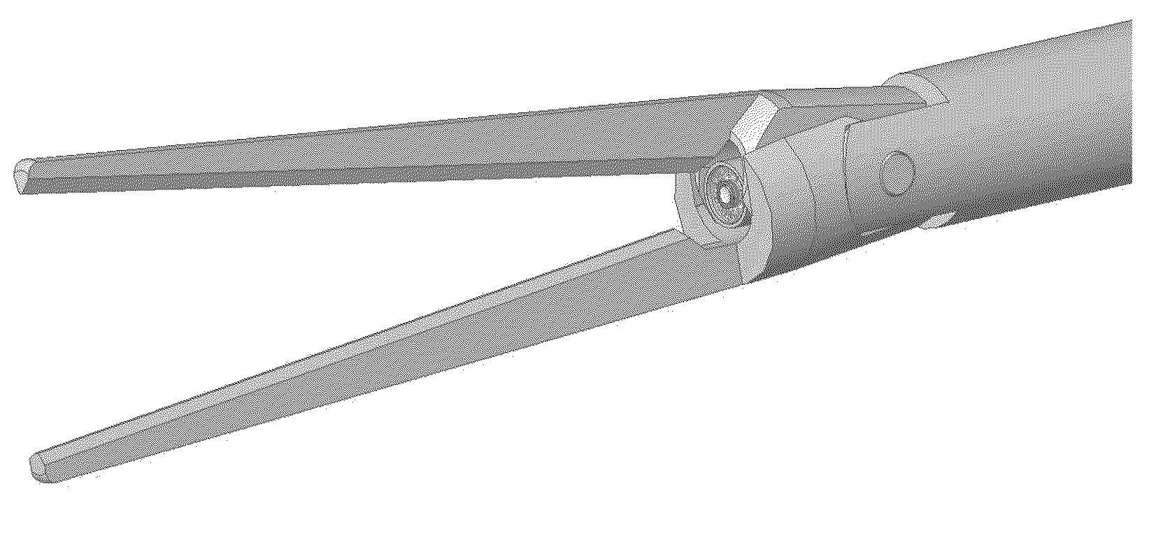
  • Small diameter video camera heads and visualization probes and medical devices containing them
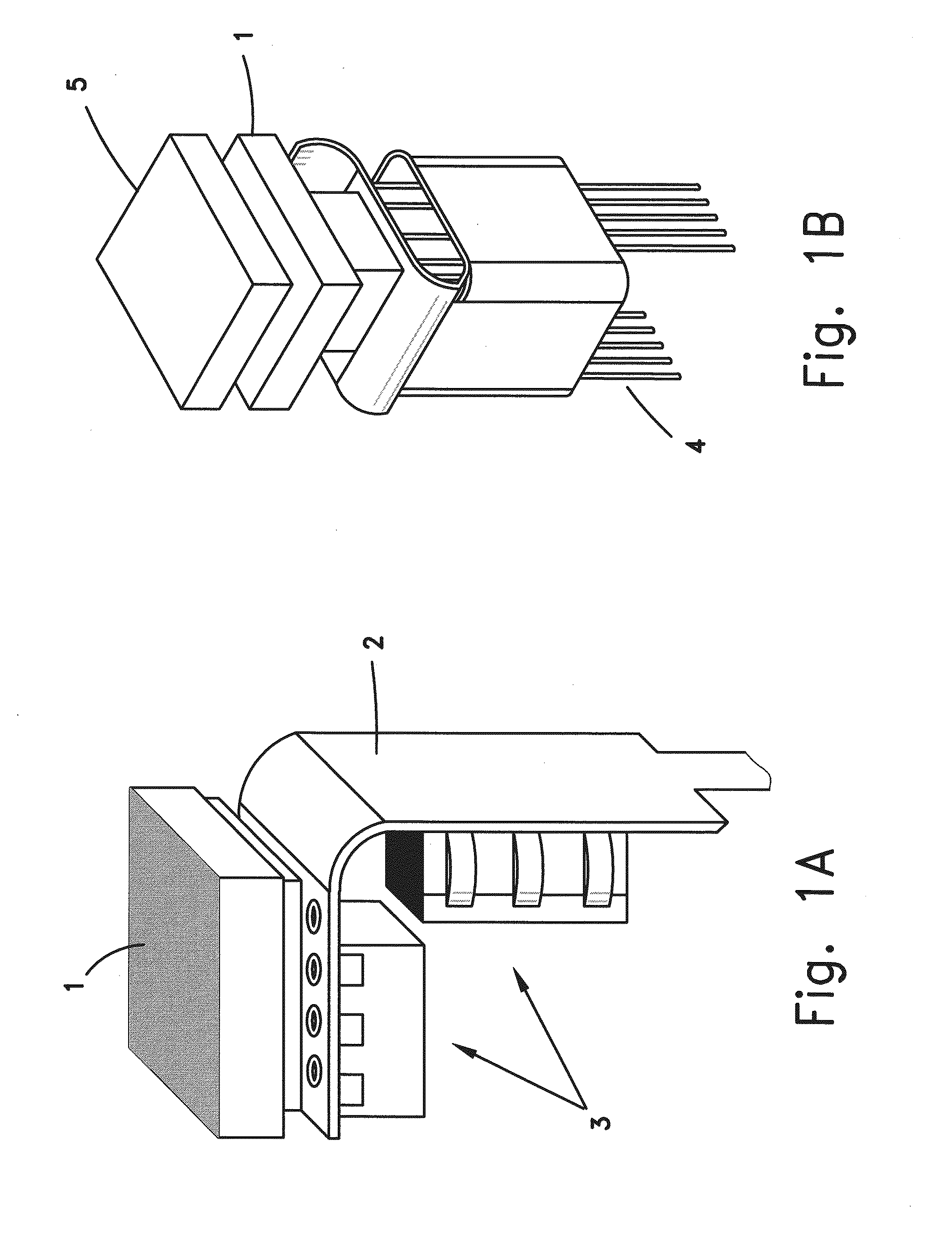
  • Small diameter video camera heads and visualization probes and medical devices containing them
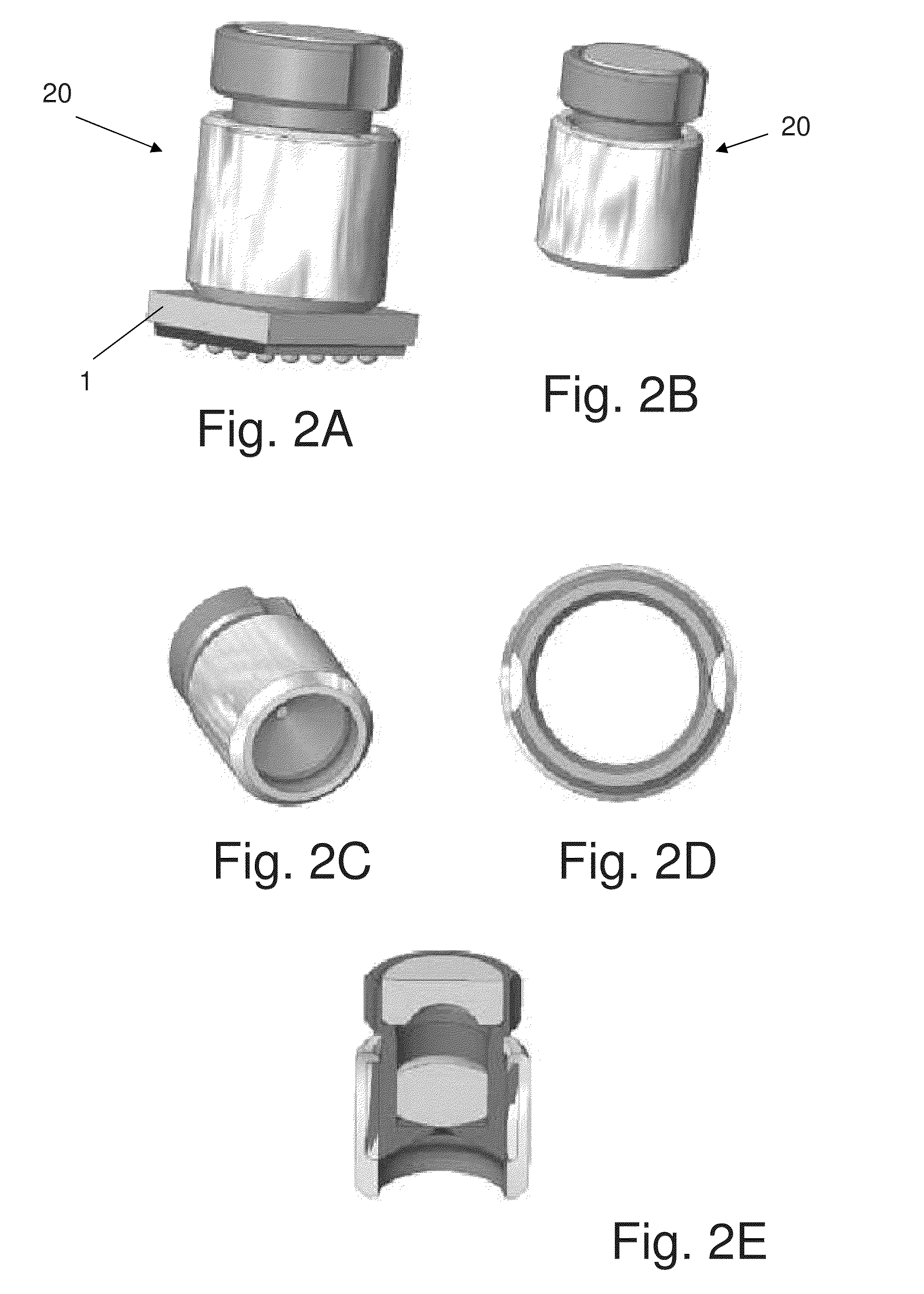
  • Small diameter video camera heads and visualization probes and medical devices containing them

Examples


Embodiment Construction

[0127]There is a considerable lack of standardization the terminology used in the literature related to digital video cameras in general and to those designed for use in endoscopic devices in particular. Herein, unless otherwise specifically mentioned, the following terminology will be used:[0128]The terms “active area”, “pixel / s area”, and “array of pixels” are used interchangeably to refer to the light receiving surface of the array of photosensitive elements, e.g. photodiodes, that convert the incoming light into electrons.[0129]The terms “sensor”, “chip”, “solid state image pick up device”, and “image pickup device” are used interchangeably to refer to the active area; to the array of microlenses that concentrate the incoming light onto the photodiodes; to the array of filters, in the case of a color sensor; and to the silicon substrate on which the active area is created. In the case of sensors manufactures by a CMOS process, these terms also can include electronics adapted to ...


PUM


Abstract

In a first aspect the invention is a video camera head comprising an objective lens assembly and a solid state imager (SSI) comprised of a solid state pick up device and additional circuitry adapted to produce an output video signal. The video camera head has a maximum outer diameter of 1.1 mm or less and the length of the objective lens assembly is 2.5 mm or less. In a second aspect the invention is a visualization probe comprising illumination means, an objective lens assembly, and a solid state imager (SSI) comprised of a solid state pick up device and additional circuitry adapted to produce an output video signal. The visualization probe has a maximum outer diameter of 2.8 mm or less. In a third aspect the invention is a medical device comprising a visualization probe comprised of illumination means, an objective lens assembly, and a solid state imager (SSI) comprised of a solid state pick up device and additional circuitry adapted to produce an output video signal. The medical device has a maximum outer diameter of 3.2 mm or less.

Description

FIELD OF THE INVENTION[0001]The present invention relates to the field of visualization tools. More particularly, the invention relates to visualization probes useful in diagnostic, therapeutic and in surgical apparatus, as well as to a variety of non-medical (e.g., industrial) applications.BACKGROUND OF THE INVENTION[0002]Visualization inside the human body is an indispensable tool to enable the physician to perform an accurate diagnosis of a variety of illnesses, to deliver therapeutic agents and / or to perform minimal invasive surgical operations inside the body. Obviously to reduce trauma for the patient, such procedures are better performed through the natural orifices of the human body, whenever possible, however sometimes it is necessary to use invasive techniques and to penetrate the human body through the skin. A very large number of endoscopic devices exist nowadays. These devices, which consist of an elongated body provided with channels through which medical devices can b...

Claims


Application Information

Patent Timeline
IPC IPC(8): H04N7/18H04N5/335
CPCA61B1/00096A61B1/0055A61B1/05A61B1/051A61B17/29H04N5/2253H04N5/2254H04N2005/2255G02B23/243H04N23/54H04N23/55H04N23/555A61B1/00087
Inventor SONNENSCHEIN, ELAZARSMOLIAR, ARIELMALKA, YUVAL
Owner SCOUTCAM LTD
Learn More