Saccadic dual-resolution video analytics camera

a dual-resolution, video analytics technology, applied in the field of systems and methods, can solve the problems of limited effectiveness of video analytics in real-world applications, limitations of conventional solutions, and major challenges, and achieve the effect of enhancing ambient illumination and improving performan

Inactive Publication Date: 2011-03-17
VIION SYST
View PDF11 Cites 192 Cited by
  • Summary
  • Abstract
  • Description
  • Claims
  • Application Information

AI Technical Summary

Benefits of technology

[0007]In order to address the issue of illumination, an infrared on-axis collimated flash may be used. This provides sufficient illumination to improve performance in dark locations, as well as locations where cast shadows affect the performance of automated object recognition systems. The illuminator flash exploits the same principal as the telephoto camera in that by aiming directly upon the object of interest, a tightly collimated beam using a small amount of illuminator power may be used to substantially augment ambient illumination.

Problems solved by technology

However, despite very high performance in laboratory testing, the effectiveness of video analytics in real-world applications remains limited.
The limitations of conventional solutions are the result of a number of system and environmental factors, such as illumination, object pose, shadows, limited resolution and noise.
In real world environments, capturing images of objects of interest (e.g., faces, individual characteristics such as irises, license plates, abandoned luggage, etc.) with sufficient resolution to permit recognition, while at the same time providing sufficient field-of-view to cover a significant area, poses a major challenge.
For example, if a camera is zoomed-out to capture objects of interest within a large area such as an entire room, corridor, entrance plaza, roadway or parking lot, the resolution of the captured images is insufficient for automated object recognition.
Video analytic systems which exploit currently available video surveillance infrastructure suffer from a lack of controlled illumination, which negatively impacts performance.

Method used


Image

  • Saccadic dual-resolution video analytics camera
  • Saccadic dual-resolution video analytics camera
  • Saccadic dual-resolution video analytics camera

Examples


Embodiment Construction

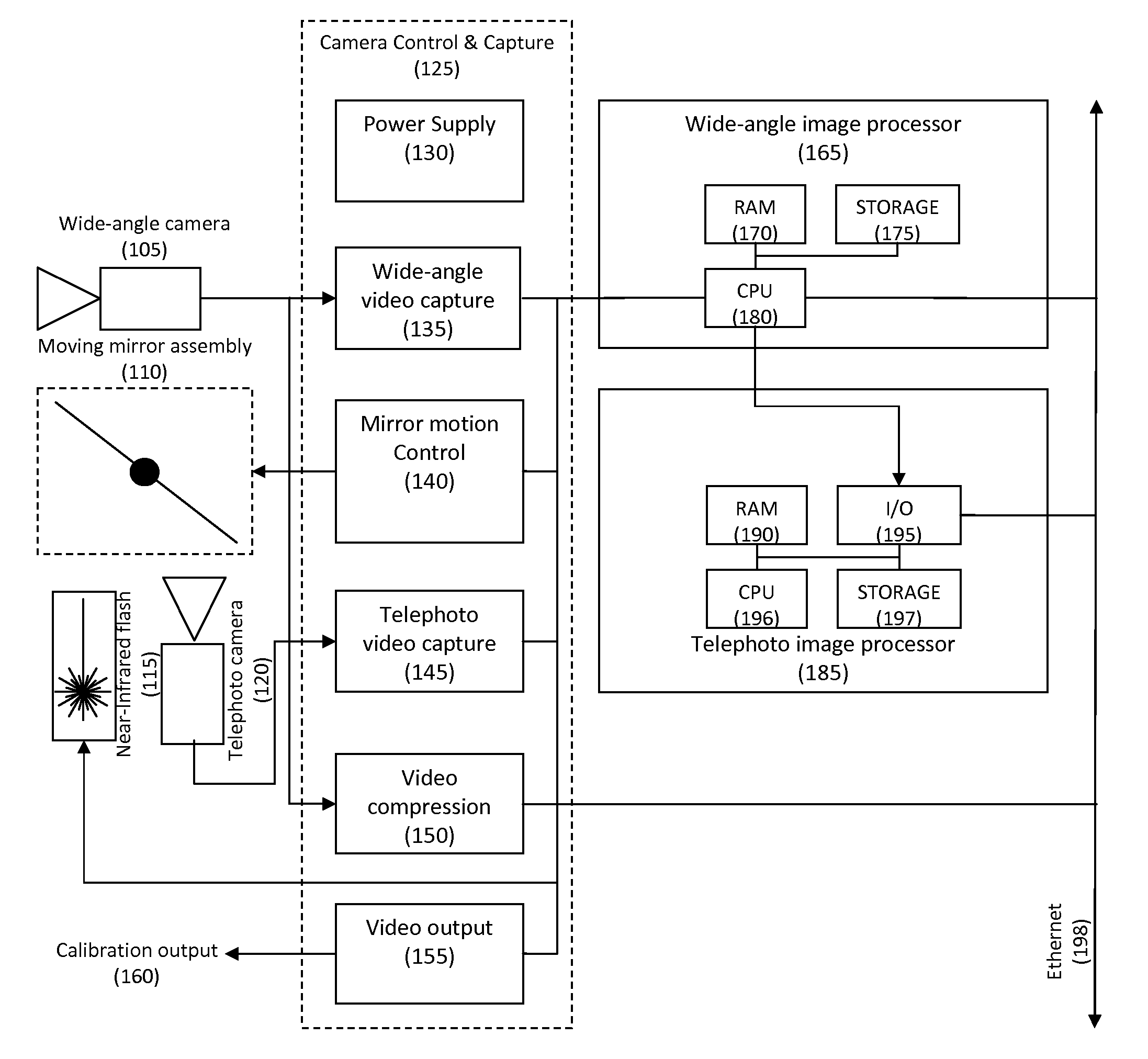
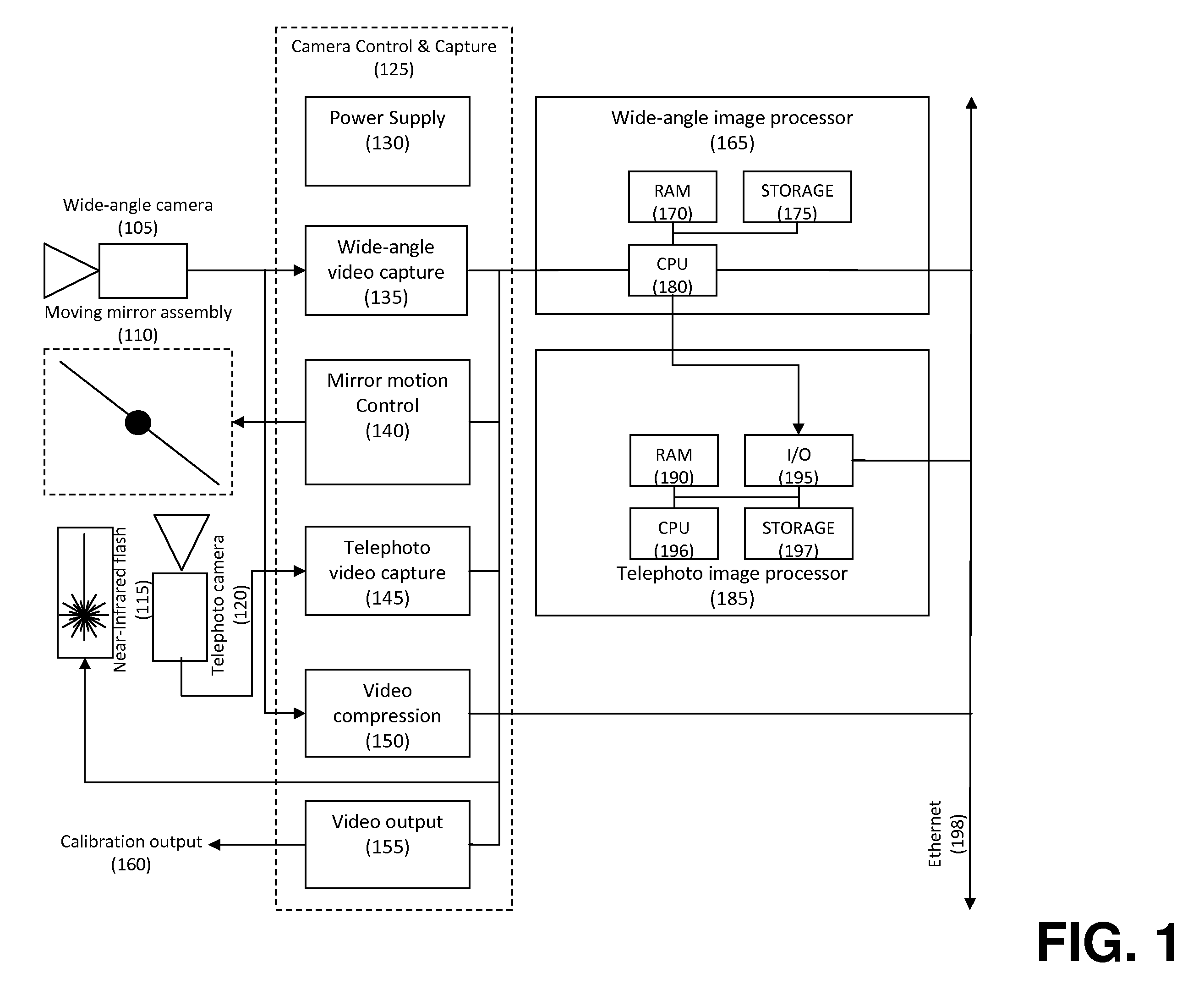
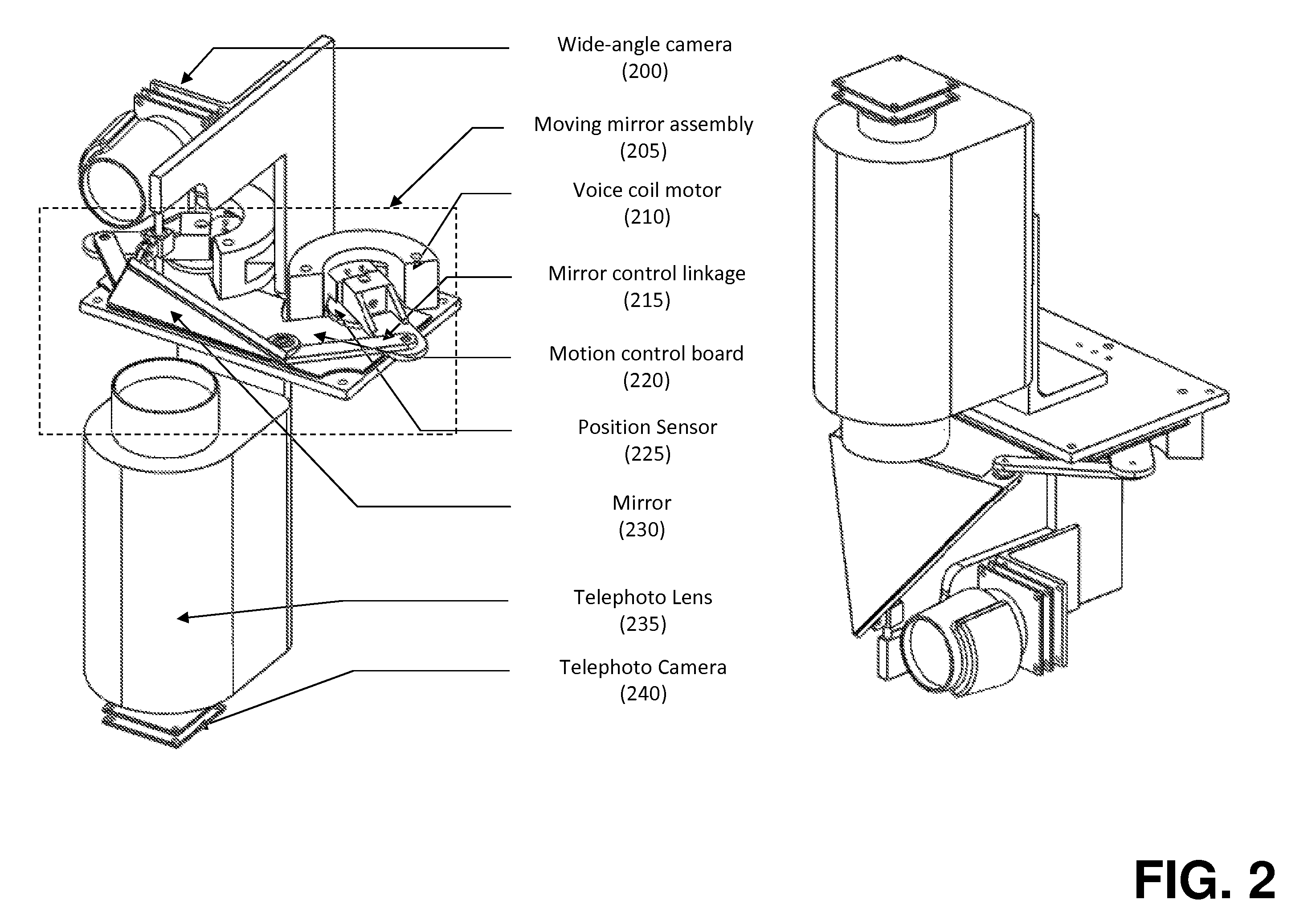
[0022]In many surveillance and image capture applications, the initial identification of an object of possible interest and the eventual positive recognition of that object may have different image capture and processing requirements. For example, it is common to survey an entire scene involving many different objects or people at different distances and angles with respect to the camera. This requires using a camera with a wide field-of-view, but the resulting resolution for any object within that camera's field is generally too low to permit object recognition. Typically, recognition of a person, a particular item, or set of characters requires higher image capture resolution and may also require more stringent illumination requirements in order to provide sufficient detail for automatic recognition. In addition to image capture constraints, to effectively detect and recognize individuals, objects of interest or license plates within a scene may require performing the tasks of pre...


PUM


Abstract

Objects of interest are detected and identified using multiple cameras having varying resolution and imaging parameters. An object is first located using a low resolution camera. A second camera (or lens) is then directed at the object's location using a steerable mirror assembly to capture a high-resolution image at a location where the object is thought to be based on image acquired by the wide-angle camera. Various image processing algorithms may be applied to confirm the presence of the object in the telephoto image. If an object is detected and the image is of sufficiently high quality, detailed facial, alpha-numeric, or other pattern recognition techniques may be applied to the image.

Description

CROSS-REFERENCE TO RELATED APPLICATIONS[0001]This application claims priority to and the benefit of U.S. provisional patent application Ser. No. 61 / 242,085, filed Sep. 14, 2009, entitled “Saccadic Dual-Resolution Video Analytics Camera.”FIELD OF INVENTION[0002]The invention relates generally to systems and methods for the detection, tracking and recognition of objects, and more specifically for detection, tracking and recognition of faces, eyes, irises and / or other facial characteristics, license plates and other objects of interest in a variety of environments and conditions.BACKGROUND[0003]Image and video processing software and systems have long sought to automatically identify individuals, license plates, left luggage and other objects and events of interest. The benefits to such applications are numerous and significant, for example: early warning systems for terror attacks, missing person detection, user identification, vehicle identification, and many others. However, despite...

Claims


Application Information

Patent Timeline
IPC IPC(8): H04N7/18G06V10/147
CPCG06K9/00255G06K9/209H04N5/2256H04N5/33H04N5/23219H04N5/247H04N5/2259G06V40/166G06V10/147H04N23/56H04N23/58H04N23/611H04N23/90H04N23/21
Inventor MCMORDIE, DAVIDKELLY, MICHAEL F.
Owner VIION SYST
Why Eureka
Try Eureka