Nozzle bar for a textile processing machine

a textile processing machine and nozzle bar technology, applied in needling machines, other washing machines, liquid/gas/vapor textile treatment, etc., can solve the problems of considerable wear and extreme stress on the nozzle opening, and achieve the effect of increasing the stiffness simplifying the manufacture of the carrier element, and increasing the cost

Inactive Publication Date: 2011-03-24
GROZ BECKERT KG
View PDF30 Cites 2 Cited by
  • Summary
  • Abstract
  • Description
  • Claims
  • Application Information

AI Technical Summary

Benefits of technology

[0011]Preferably, the input orifice as well as the output orifice of the fluid channel has the shape of a slit in the direction of extension of the nozzle bar. This simplifies the manufacture of the carrier element. Instead of several bores that—as in prior art—are respectively associated with one nozzle opening of the foil, several nozzle openings are associated with one fluid channel in accordance with the invention. In comparison with many bores, the fabrication of a few slit-like recesses in the carrier element is significantly more cost-effective. In a preferred embodiment, the nozzle openings in the foil are arranged at uniform distances in a row along a slit-shaped fluid channel and its input orifice.
[0012]Considering a preferred embodiment, the nozzle bar comprises exactly one carrier element to which several foils are fastened. In so doing, each foil may be associated with a separate fluid channel of the carrier element. Consequently each of the nozzle openings of a foil is associated with one of the fluid channels of the carrier element. Consequently, the carrier element extending in a longitudinal direction comprises several discrete fluid channels, thus increasing the stiffness of the carrier element compared with a carrier element having one continuous fluid channel extending in longitudinal direction. The stiffness can be further improved in that the slit-shaped fluid channels are provided in the carrier element so as to be inclined with respect to the longitudinal direction. Preferably, the fluid channels e

Problems solved by technology

The nozzle openings are subject to extremely high stress because the water may be subject t

Method used


Image

  • Nozzle bar for a textile processing machine
  • Nozzle bar for a textile processing machine
  • Nozzle bar for a textile processing machine

Examples


Embodiment Construction

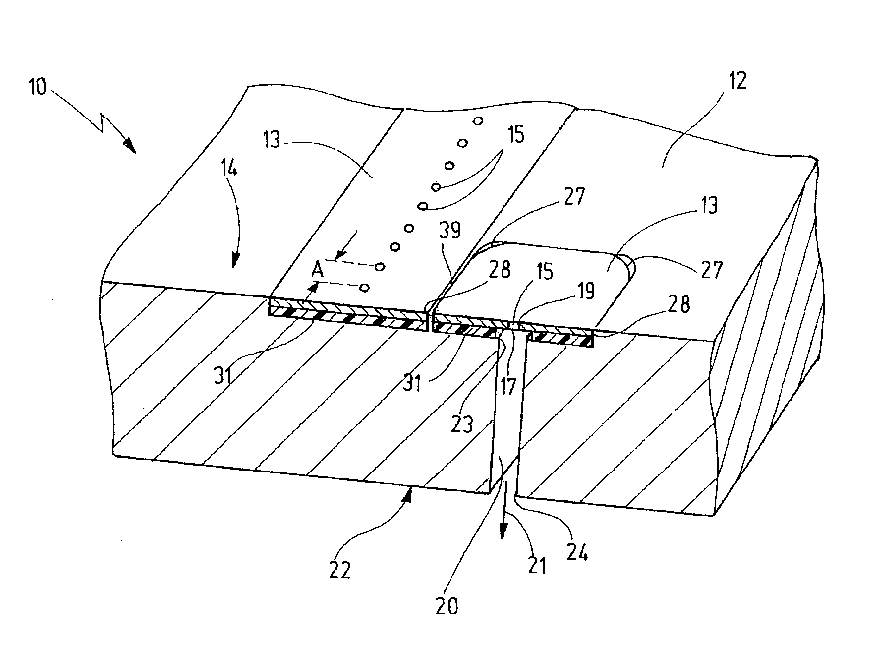
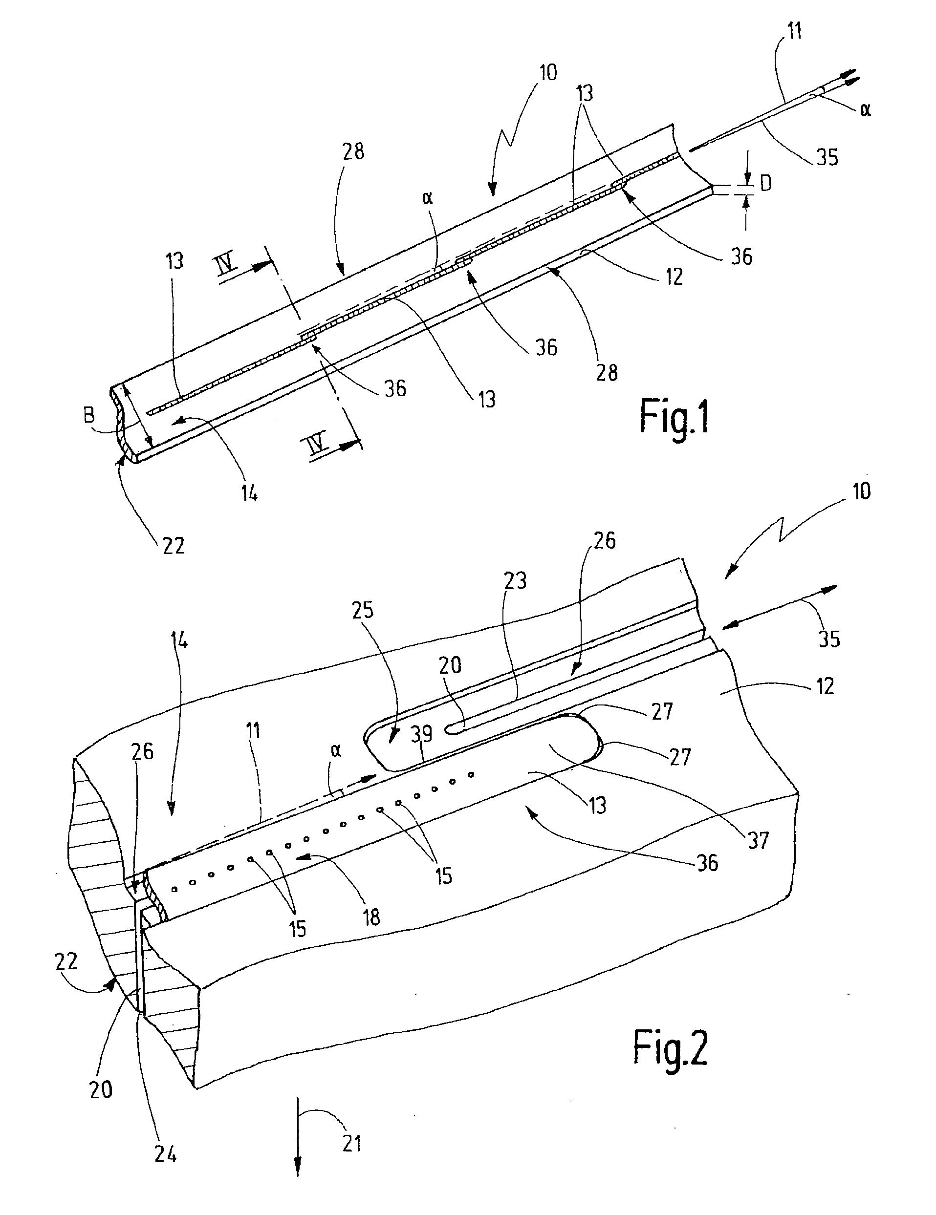
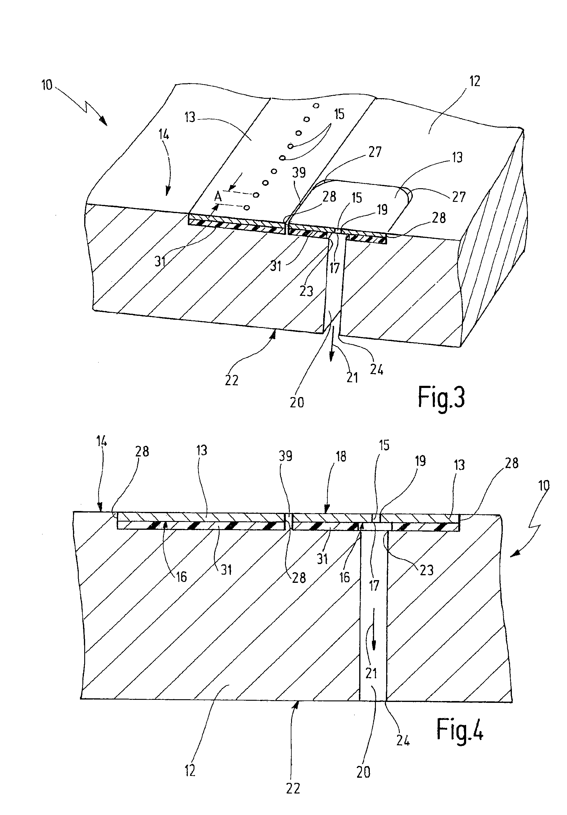
[0023]The invention relates to a nozzle bar 10 comprising a carrier element 12 extending in a longitudinal direction 11, and several foils 13. The length of the carrier element 12 in longitudinal direction 11 may vary depending on the textile machine in which the nozzle bar 10 is installed and may have a length of up to several meters. Referring to the exemplary embodiment as in FIG. 1, the carrier element 12 may have a rectangular cross-section including a fluid exit side 22, a fluid entry side 14, and two narrow flat sides 28. The width B of the carrier element may be 10 mm to approximately 30 mm, and the thickness D may be approximately 1-4 mm.

[0024]Depending on the length of the carrier element 12 and thus of the nozzle bar 10, said nozzle bar is associated with several strip-shaped foils 13 that also display a rectangular cross-section. Referring to the exemplary embodiment, the foils 13 have a length of approximately 90-100 mm. They have thickness of 0.1-0.2 mm and a width of ...


PUM

PropertyMeasurementUnit
Angleaaaaaaaaaa
Sizeaaaaaaaaaa
Shapeaaaaaaaaaa

Abstract

A nozzle bar (10) comprising a carrier element (12) provided with several slit-shaped fluid channels (20), each associated with a foil (13) having a plurality of nozzle openings (15). In the position of use, the foil (13) is arranged over an input orifice (23) of the associate fluid channel (20) so that its nozzle openings (15) are located inside the contour of its associated fluid entry opening (19). In this position of use, each foil (13) is fastened to a plane attachment surface of the carrier element (12). The attachment surface may be the bottom (26) of a groove-like recess (25) in the carrier element (12). A separate recess (25) is provided for each foil (13). The carrier element (12) can be used for numerous different types of foils. The distance of the nozzle openings (15) of the foil (13), or the size or the form of the nozzle openings (15) may vary among various foil types, without requiring modifications on the carrier element (12).

Description

CROSS-REFERENCE TO RELATED APPLICATION[0001]The present application claims the priority of European Patent Application No. 09 011 907.3, filed Sep. 18, 2009, the subject matter of which, in its entirety, is incorporated herein by reference.BACKGROUND OF THE INVENTION[0002]The invention relates to a nozzle bar for a textile processing machine.[0003]In order to compact fleece materials the use of textile processing machines has been known, wherein water is ejected at high pressure in very fine thin jets onto random fiber nonwovens. In so doing, the water jets take over the function of felting needles and of intertwining the fibers of the random fiber nonwoven in order to produce a compact fleece material.[0004]To accomplish this, the textile machine comprises a nozzle bar containing a plurality of nozzle openings through which the water is formed into fine, needle-like water jets. The nozzle openings are subject to extremely high stress because the water may be subject to high pressur...

Claims


Application Information

Patent Timeline
IPC IPC(8): D06B1/00D04H1/492
CPCB05B1/14D04H18/04D04H1/492B05B15/065B05B15/65
Inventor EYDNER, REINHOLDSCHMID, THOMASSPILL, JURGENLOCHER, ACHIM
Owner GROZ BECKERT KG
Why Eureka
Try Eureka