Control Valve

a control valve and valve body technology, applied in the field of control valves, can solve the problems of high raw material prices, extended material, and high cost per se, and achieve the effects of saving material, saving material, and simplifying machining

Active Publication Date: 2011-03-24
FRESE AS
View PDF4 Cites 33 Cited by
  • Summary
  • Abstract
  • Description
  • Claims
  • Application Information

AI Technical Summary

Benefits of technology

[0011]When the valve housing is made in one piece by casting or forging, an additionally simplified machining is achieved, as machining of associated joining faces on valve housing parts is avoided, just as it is possible to achieve a saving material.
[0012]When the pressure maintaining arrangement and the amount control arrangement are mounted in the same opening in the valve housing, a saving of material is likewise achieved.
[0013]When the cooperating coaxial cylinder shell faces are given the same axial movement, a control valve having a more unique, reproducible and safe function in response to the impact from the external actuator is achieved.
[0014]When the object is configured such that the cooperating downstream cylinder shell face is surrounded fully or partly by the throttle member, a saving of material is likewise achieved.

Problems solved by technology

The drawbacks of this control valve are not related to the function of the valve, but are caused in particular by the high raw material prices, such as of copper, which constitutes a substantial proportion of the brass alloys used as profile rods as a starting material for many inner components in such control valves.
Control valves require much machining of many different objects, which are mainly of brass, which per se is very costly and moreover involves losses in the sense that the copper-containing brass material purchased in rod shape for the production has a price per kg which is considerably higher than the sales price per kg of the same brass alloy, which is sold as chips from the object production for renewed processing into rod material.
This permanent pressure impact on the diaphragm wears and extends the material, which is weakened thereby.

Method used


Image

  • Control Valve
  • Control Valve
  • Control Valve

Examples


Embodiment Construction

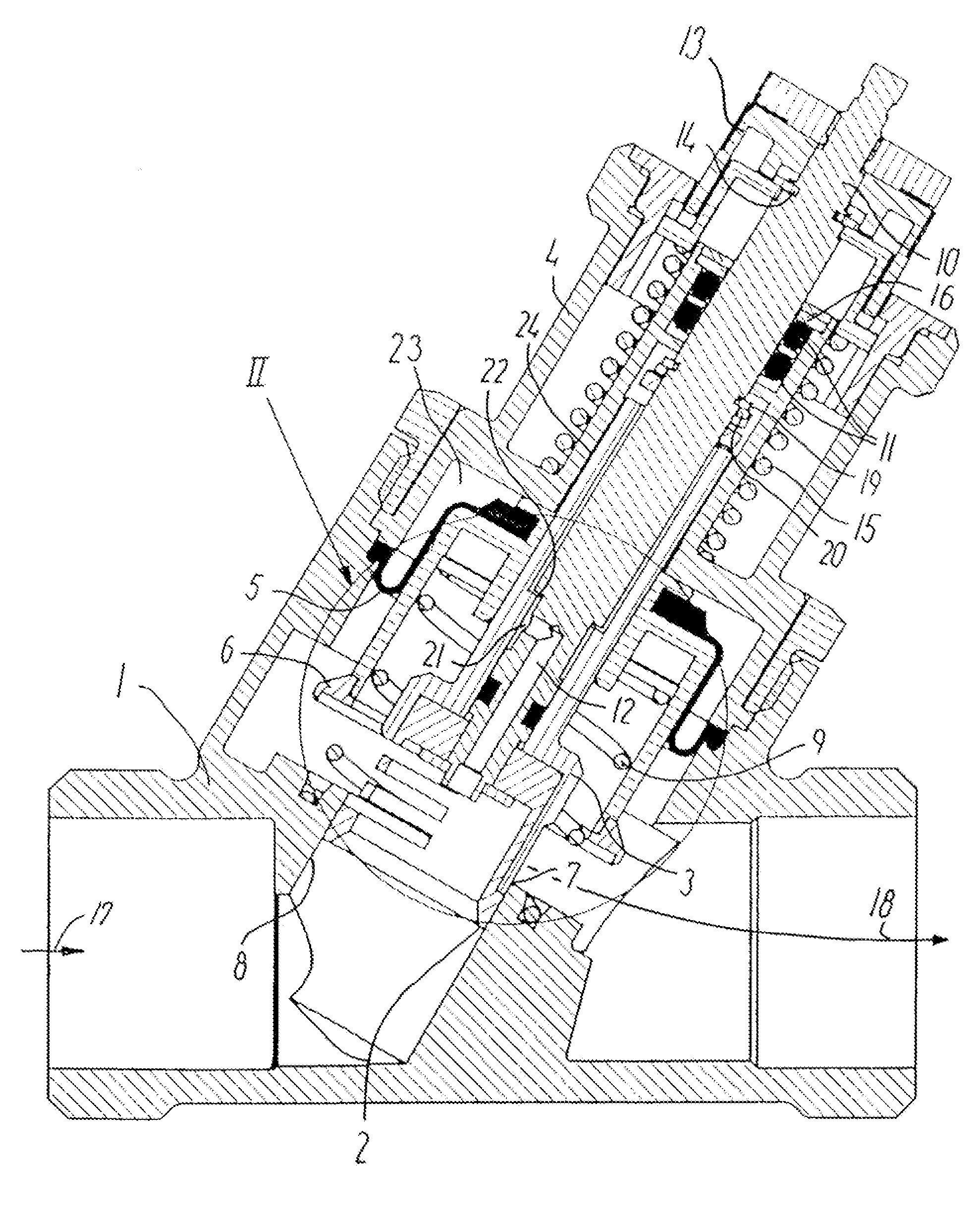
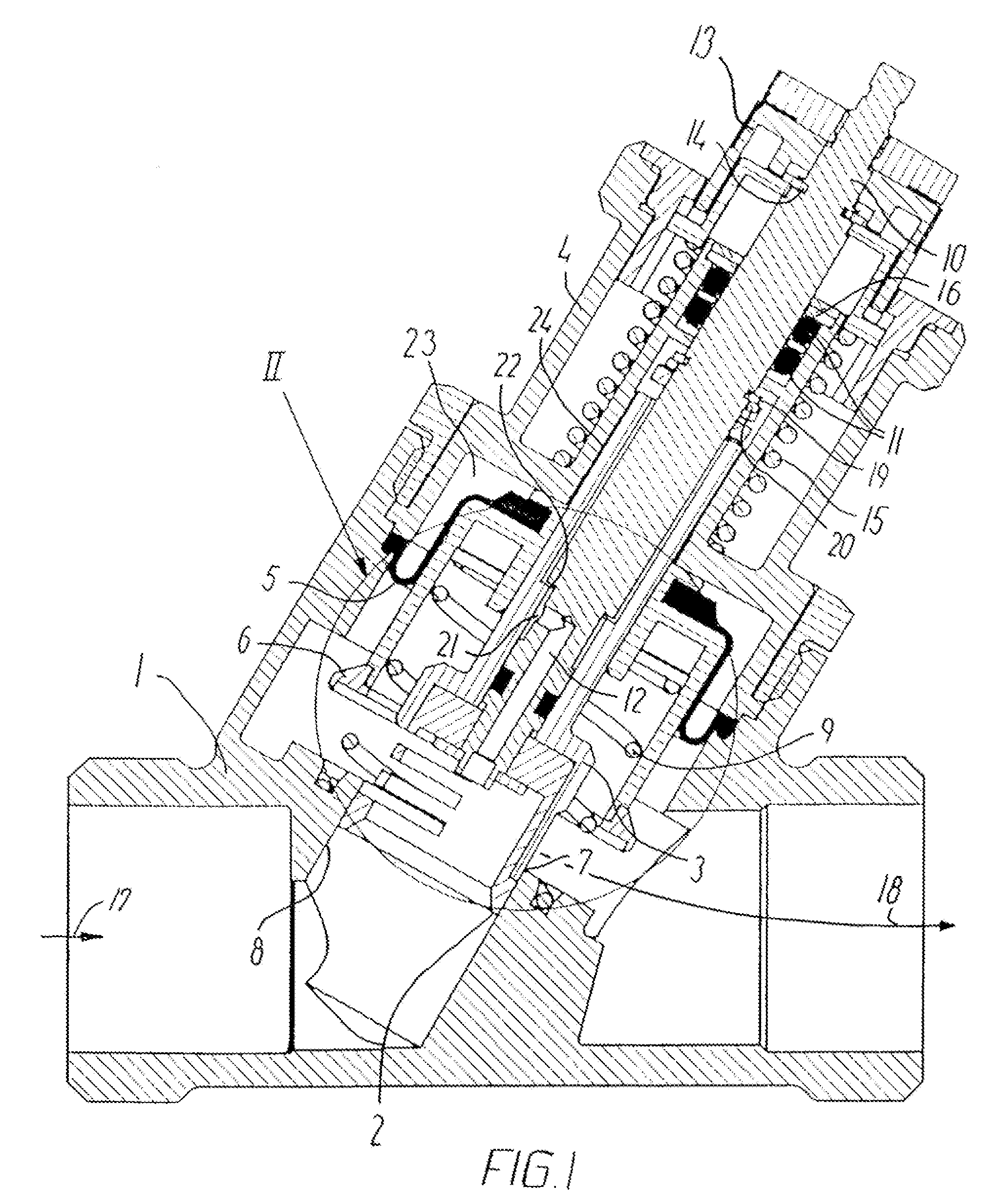
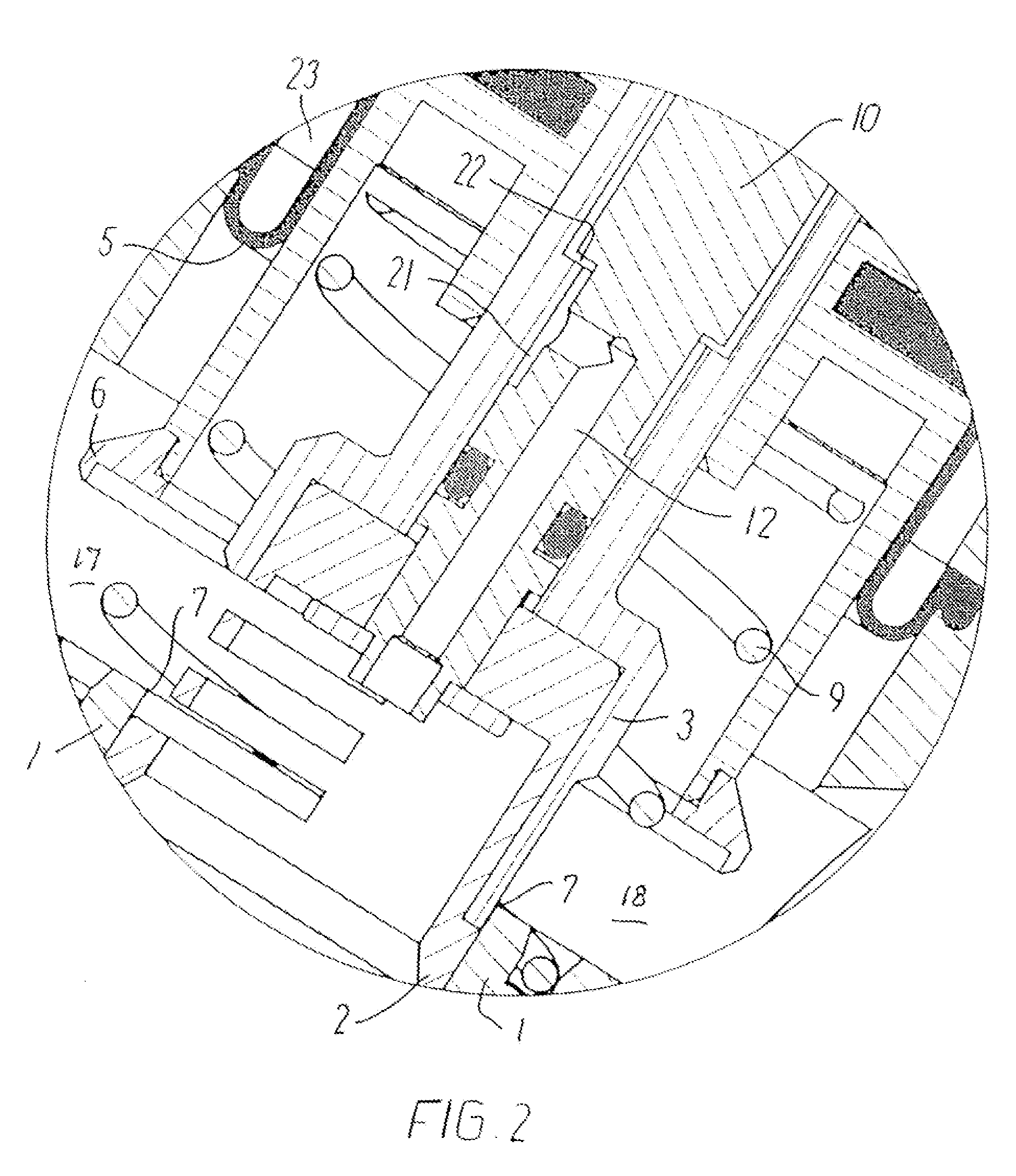
[0021]In FIG. 1, a control valve according to the invention is shown in a sectional view, consisting of a valve housing 1 having on inlet 17 and an outlet 18. The pressure maintaining mechanism consists of a rolling diaphragm 5 and a throttle member 6 which supports the rolling diaphragm. The pressure at the inlet 17 is transferred to the outer side 23 of the rolling diaphragm 5 through a bore 12 in the spindle 10 and a capillary channel 22 between the spindle and the cylinder shell element 3. From there, the inlet pressure will propagate along the outer side 24 of the cylinder shell element 5 to the space 23 and thereby the outer side of the diaphragm 5.

[0022]A spring 9 urges the throttle member 6 to its top position in cooperation with the pressure within the closing diameter of the throttle member 6.

[0023]In use, a balance is established between the inlet pressure 17 and the outlet pressure 18 plus the spring force from the spring 9. This differential pressure will therefore be c...


PUM


Abstract

The control valve according to the invention is for use in liquid carrying systems. It comprises a valve housing (1) having an inlet side (17) and an outlet side (18), said valve housing being provided with a pressure maintaining arrangement for maintaining a constant differential pressure between the inlet and outlet sides, as well as an amount control arrangement for setting the maximum flow amount through the valve and adjustment of it. The control arrangement comprises two cylinder shell elements (2 and 3) cooperating in the flow path, both having material removed from otherwise overlapping areas, thereby generating an uncovered area (25) in the flow path of the control valve. The outer cylinder shell element (3) is stationary rotatable relative to the valve housing, while the inner cylinder shell element (2) may be rotated by means of a rotatable handle (13), whereby a larger or smaller opening (25) between the cooperating cylinder shell elements (2 and 3) may be provided. Both cylinder shell elements (2 and 3), which cooperate with the seat hole (8) of the valve housing, may also be displaced (26) in the axial direction, resulting in an increase or a decrease of the generated opening (25). Thereby, the flow amount may be adjusted prior to the presetting, e.g. by means of an actuator.

Description

THE PRIOR ART[0001]The invention relates to a control valve having an inlet side and an outlet side in a valve housing, in which a pressure maintaining arrangement is mounted for maintaining a constant differential pressure between the inlet and outlet sides, said assembly comprising a rolling diaphragm and a throttle member which sets itself in a balance between the inlet pressure and the outlet pressure as well as between the inlet pressure on the one hand and the outlet pressure as well as spring force on the other hand, respectively and with an amount control arrangement having an adjustable basic setting and a flow opening reducing arrangement, which may be activated via a spindle connected with an actuator, wherein the amount control is established by mutual rotation of an orifice having cooperating outer and inner slide shell faces, and wherein the reduction of the flow established by means of the actuator as a basic setting takes place by axial movement of the downstream cyl...

Claims


Application Information

Patent Timeline
Patent Type & Authority Applications(United States)
IPC IPC(8): F16K31/12
CPCG05D7/0106F16K3/32F16K3/26F16K1/526Y10T137/7797Y10T137/7811Y10T137/7796Y10T137/7782Y10T137/7788Y10T137/782Y10T137/7801
Inventor JORGENSEN, AGNES
Owner FRESE AS
Why Eureka
Try Eureka