Rotational angle sensor, motor, rotational angle detector, and electric power steering system

a technology of rotational angle and sensor, which is applied in the direction of instruments, galvano-magnetic devices, and magnetic field measurement using galvano-magnetic devices, can solve the problems of high cost of producing coil-type resolver, difficulty in downsizing a coil-type resolver, and remains a problem to be solved, and achieves simple configuration and high degree of accuracy

Active Publication Date: 2011-03-24
JTEKT CORP
View PDF1 Cites 36 Cited by
  • Summary
  • Abstract
  • Description
  • Claims
  • Application Information

AI Technical Summary

Benefits of technology

[0011]It is an object of the invention to provide a magnetic rotational angle sensor which has a simple configuration, which detects the rotational angle with a high degree of accuracy, and in which the number of magnetic poles may be flexibly changed, a motor that has the rotational angle sensor, a rotational angle detector that has the rotational angle sensor, and an electric power steering system.
[0014]With the configuration described above, each of the three-phase sensor signals output from each of the sensor devices overlaps with one of the sensor signals output from each of the remaining sensor devices. Then, the sensor signals of which the phases overlap each other are averaged. As a result, it is possible to obtain the three-phase sinusoidal waveforms that are free from distortion and correspond to the rotation of the magnet rotor. As a result, it is possible to more accurately detect the rotational angle with a simple configuration. In addition, it is possible to more flexibly change the number of the magnetic poles. Further, because multiple sensor devices are provided, even if a malfunction occurs in one of the sensor devices, it is possible to continue rotational angle detection based on the sensor signals output from the remaining two sensor devices. As a result, it is possible to improve the reliability.

Problems solved by technology

However, it is difficult to downsize a coil-type resolver because the coil-type resolver has coils.
As a result, the cost of producing the coil-type resolver is high.
However, even if the above-described configuration is employed, there still remains a problem to be solved.

Method used


Image

  • Rotational angle sensor, motor, rotational angle detector, and electric power steering system
  • Rotational angle sensor, motor, rotational angle detector, and electric power steering system
  • Rotational angle sensor, motor, rotational angle detector, and electric power steering system

Examples


Embodiment Construction

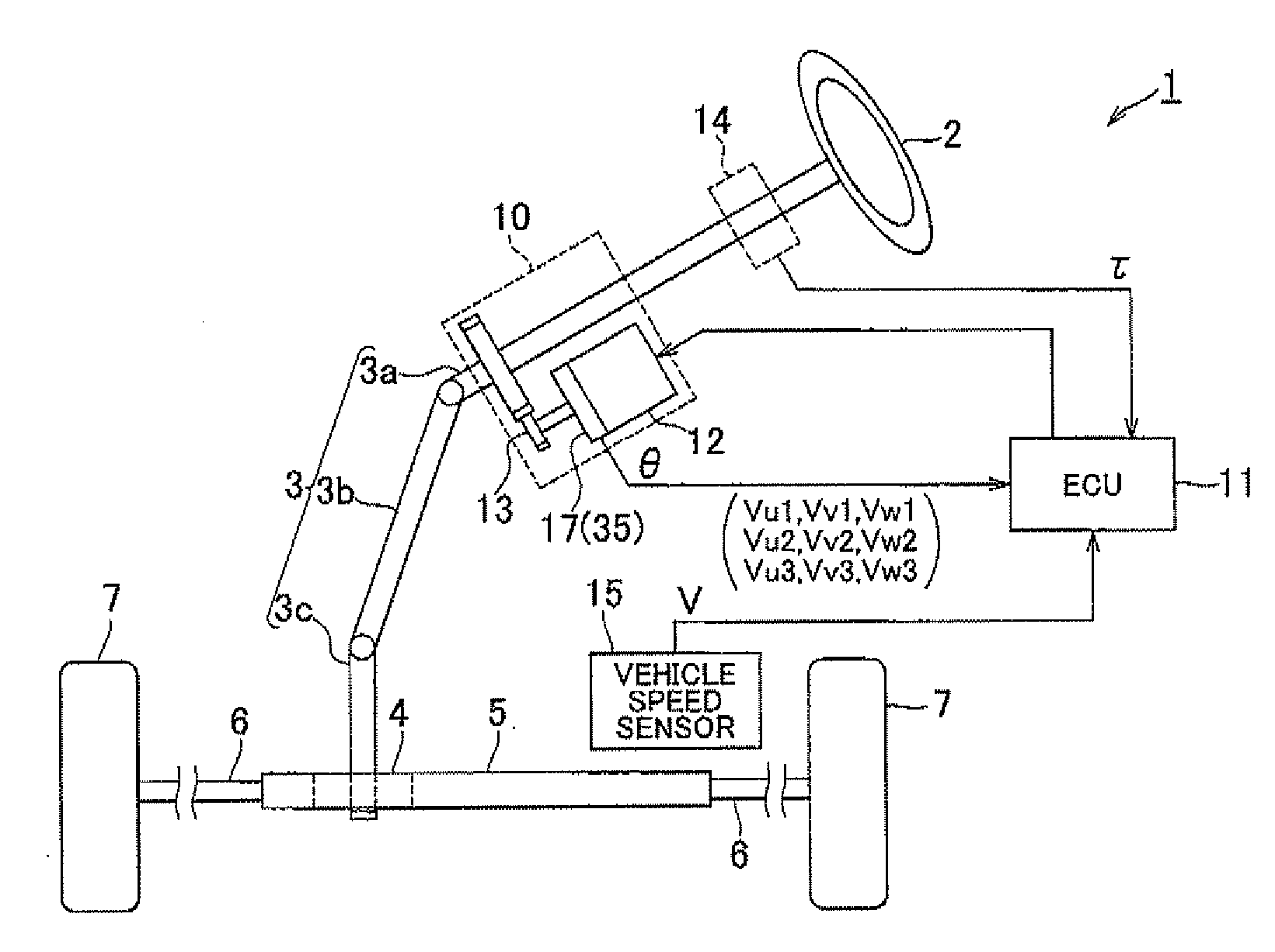
[0032]Hereafter, an embodiment of the invention will be described with reference to the accompanying drawings. As shown in FIG. 1, in an electric power steering system (EPS) 1 according to the embodiment, a steering shaft 3 to which a steering wheel 2 is secured is connected to a rack shaft 5 via a rack-and-pinion mechanism 4. The rotation of the steering shaft 3, caused by a steering operation, is converted into linear reciprocation motion of the rack shaft 5 by the rack-and-pinion mechanism 4. The steering shaft 3 is formed by connecting a column shaft 3a, an intermediate shaft 3b, and a pinion shaft 3c to each other. The linear reciprocation motion of the rack shaft 5, caused by the rotation of the steering shaft 3, is transmitted to knuckles (not shown) via tie-rods 6 connected to respective ends of the rack shaft 5. As a result, the steering angle of steered wheels 7, that is, the direction in which a vehicle travels is changed.

[0033]The EPS 1 includes an EPS actuator 10 and an...


PUM


Abstract

A rotational angle sensor includes: a magnet rotor in which multiple magnetic poles are formed along the circumferential direction of the magnet rotor; and three sensor devices that are arranged on a circle concentric with the magnet rotor at regular angle intervals. Each of the sensor devices includes three half-bridge circuits each of which has a pair of spin valve magnetic resistances that are connected in series in such a manner that the magnetization directions of spin fixed layers of the spin valve magnetic resistances are opposite to each other. Each of the sensor devices is formed in such a manner that phases of the sensor signals output from the respective half-bridge circuits based on a change in magnetic flux caused by the rotation of the magnet rotor are offset from each other by an electrical angle of 120°.

Description

INCORPORATION BY REFERENCE[0001]The disclosure of Japanese Patent Application No. 2009-218800 filed on Sep. 24, 2009 including the specification, drawings and abstract is incorporated herein by reference in its entirety.BACKGROUND OF THE INVENTION[0002]1. Field of the Invention[0003]The invention relates to a rotational angle sensor, a motor that has the rotational angle sensor, a rotational angle detector that has the rotational angle sensor, and an electric power steering system.[0004]2. Description of the Related Art[0005]When a motor is required to rotate smoothly and highly quietly, for example, when a motor is used in an electric power steering system (EPS), the operation of the motor is usually controlled by supplying sinusoidal currents, of which the phases are offset from each other by an electrical angle of 120°, to a U-phase coil, a V-phase coil and a W-phase coil. Therefore, a coil-type resolver that detects a rotational angle with a high degree of accuracy is convention...

Claims


Application Information

Patent Timeline
Patent Type & Authority Applications(United States)
IPC IPC(8): G01B7/30
CPCG01D5/145
Inventor SAKAI, KAZUYA
Owner JTEKT CORP
Why Eureka
Try Eureka