Magnetic resonance imaging apparatus and magnetic resonance imaging method

a magnetic resonance imaging and magnetic resonance imaging technology, applied in the field of magnetic resonance imaging, can solve the problems of spatial resolution degrade, limit in terms of temporal resolution, and inability to obtain sufficient contrast, and achieve satisfactory time resolution

Active Publication Date: 2011-03-24
TOSHIBA MEDICAL SYST CORP
View PDF14 Cites 70 Cited by
  • Summary
  • Abstract
  • Description
  • Claims
  • Application Information

AI Technical Summary

Benefits of technology

[0013]The present invention aims to provide MRI technology which can safely acquire “MRA imaging region including a heart” and “blood flow information based on the MRA image” with satisfactory time resolution and spatial resolution.
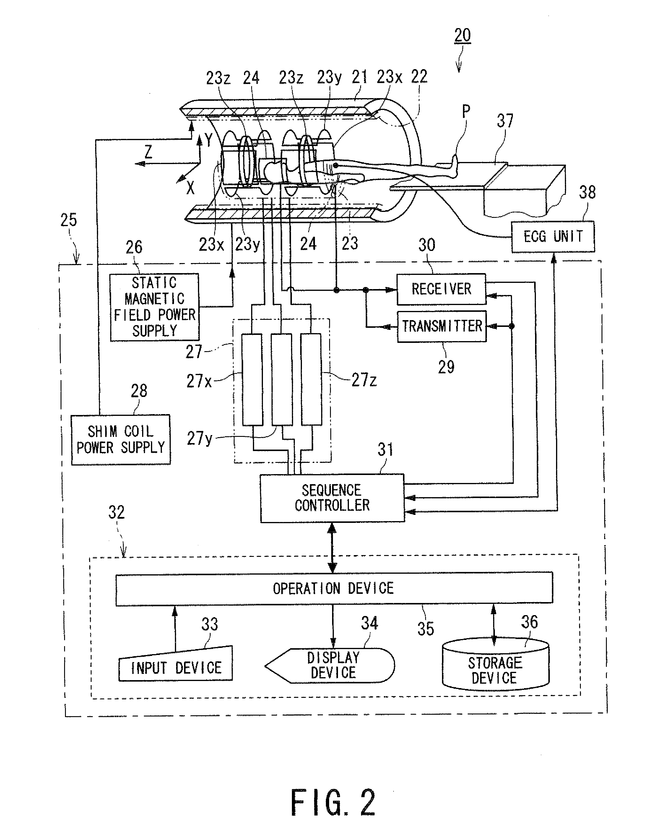
[0020]According to the magnetic resonance imaging apparatus or the magnetic resonance imaging method configured as described above, MRA image data of an imaging region including heart and blood flow information based on the MRA images can be acquired safely with satisfactory time resolution and spatial resolution.

Problems solved by technology

Therefore, imaging timing is restricted to the period where contrast medium is washed-out in the normal tissue and still in the infarction area after administering a contrast medium, otherwise sufficient contrast can not be obtained.
Thus, it has a limit in terms of temporal resolution as a problem.
Additionally, spatial resolution also degrades due to the restriction of time resolution.
Under the aforementioned technical background, there is a problem that image quality varies and diagnosis varies among readers.
Furthermore, in stress perfusion test, risk of medication such as adenosine and dipyridamole is also a huge concern.
The aforementioned problems apply to a case in which CE MRA imaging is acquired for various imaging regions.

Method used


Image

  • Magnetic resonance imaging apparatus and magnetic resonance imaging method
  • Magnetic resonance imaging apparatus and magnetic resonance imaging method
  • Magnetic resonance imaging apparatus and magnetic resonance imaging method

Examples


first modification

1. First Modification

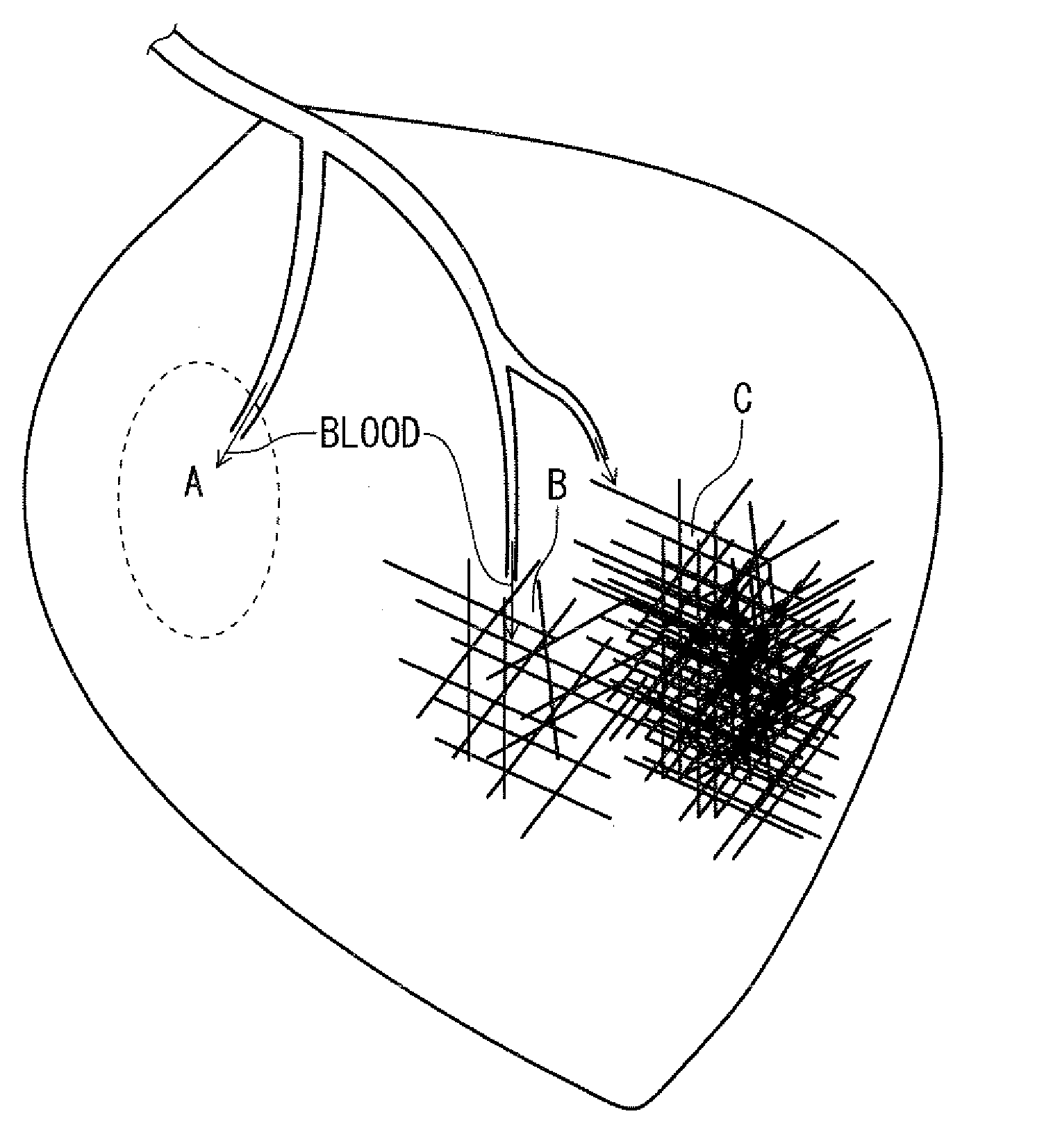
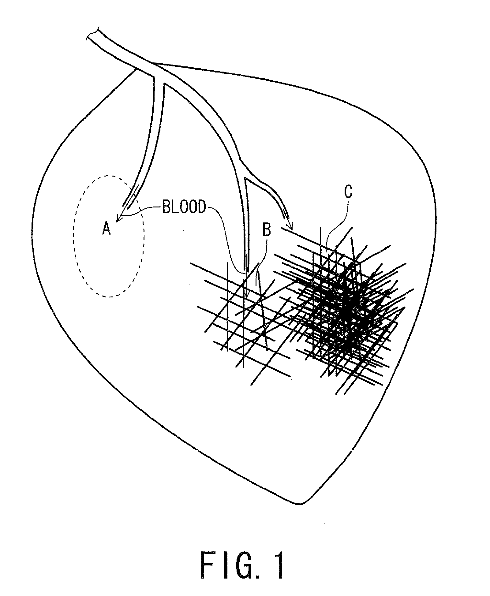
[0211]In the aforementioned embodiment, an example of applying spatial selective 180° IR pulses as spatial selective excitation pulses for distinguishing signal of blood flowing into the imaging region is explained. However, this invention is not limited to such configuration. A 90° saturation pulse can be used as the spatial selective excitation pulse. When a 90° saturation pulse is applied as the spatial selective excitation pulse, a time interval from application timing of the 90° saturation pulse to start timing of data acquisition is set to a different value from the time interval in the case of applying the first and second spatial selective 180° IR pulse as the spatial selective excitation pulses (refer to FIG. 4 and FIG. 5). For example, blood of unsaturated state flowing from the outside of the imaging region into the imaging region can be selectively emphasized, when imaging is performed under the following 2 conditions. That is (A) the imaging region ...

second modification

2. Second Modification

[0213]In the aforementioned embodiment, an example of imaging under application of neither medicational stress nor exercise stress is explained. However, this invention is not limited to such configuration. Imaging may be performed applying both medication stress and exercise stress. Moreover, by performing the following 2 imaging sequences (X) and (Y) respectively, acquired blood flow images may be displayed in parallel so that blood flow images acquired in the imaging sequences (X) and (Y) can be compared with each other. In this case, both of medicational stress and exercise stress or either of them are(is) applied in the imaging sequence (X), whereas neither medicational stress nor exercise stress is applied in the imaging sequence (Y). Additionally, blood flow image data for diagnosis can be generated and their images can be displayed by performing differential processing between “the blood flow image data acquired under application of stress to an object”...


PUM


Abstract

According to one of the aspects of an MRI apparatus of the present invention, the MRI apparatus includes an imaging data acquiring unit and a blood flow information generating unit. The imaging data acquiring unit acquires imaging data from an imaging region including myocardium, without using a contrast medium, by applying a spatial selective excitation pulse to a region including at least a part of an ascending aorta for distinguishably displaying inflowing blood flowing into the imaging region. The blood flow information generating unit generates blood flow image data based on the imaging data.

Description

BACKGROUND OF THE INVENTION[0001]1. Field of the Invention[0002]The present invention relates to MRI (magnetic resonance imaging) which magnetically excites nuclear spin of an object with an RE (radio frequency) signal having the Larmor frequency and reconstructs an image based on NMR (nuclear magnetic resonance) signals generated due to the excitation.[0003]More particularly, the present invention relates to a magnetic resonance imaging apparatus and a magnetic resonance imaging method which can perform MRA (Magnetic Resonance Angiography) for acquiring a blood flow image without using a contrast medium.[0004]2. Description of the Related Art[0005]Magnetic Resonance Imaging is an imaging method which magnetically excites nuclear spin of an object set in a static magnetic field with an RF signal having the Larmor frequency and reconstructs an image based on NMR signals generated due to the excitation.[0006]In the field of the magnetic resonance imaging, MRA is known as a method of o...

Claims


Application Information

Patent Timeline
Patent Type & Authority Applications(United States)
IPC IPC(8): A61B5/055
CPCG01R33/4833G01R33/543G01R33/5601A61B5/029G01R33/5635G01R33/56366G01R33/5608A61B5/0037A61B5/318A61B5/0263A61B5/7271A61B5/742G01R33/385
Inventor MIYAZAKI, MITSUEKUHARA, SHIGEHIDE
Owner TOSHIBA MEDICAL SYST CORP
Why Eureka
Try Eureka