Air cushion sensor for tactile sensing during minimally invasive surgery

a sensor and air cushion technology, applied in the field of sensor for providing force feedback, can solve the problems of difficult to sense the actual contact force between the tool and the tissue, the difficulty of the mis, and the inability of surgeons to palpate and feel the organs with their hands, so as to achieve accurate steering and less risk of tissue damag

Inactive Publication Date: 2011-03-24
KING'S COLLEGE LONDON
View PDF12 Cites 30 Cited by
  • Summary
  • Abstract
  • Description
  • Claims
  • Application Information

AI Technical Summary

Benefits of technology

[0025]An object of the invention is to provide a sensor which is manoeuvrable and which can be used to give haptic feedback, i.e. tactile and/or force information. In one embodiment this allows the fast creation of mechanical images showing the stiffness and/or f

Problems solved by technology

However, MIS (also referred to as keyhole surgery) does have some major drawbacks according to [4].
First of all, the lack of direct access to the surgical site makes it impossible for surgeons to palpate and feel organs with their hands.
Another problem is that the friction between the laparoscopic tools and the trocar port and also the torque required to rotate the tools make it very difficult to sense the actually contact forces between the tool and tissue.
This fallback increases the possibility of accidental tissue trauma.
The third limitation is the loss of direct hand-eye coordination due to the fact that tools have to move around a fixed point reducing the degrees of freedom to four (excluding the tip's motion): pitch, yaw, roll and insertion [5].
None of the robotic systems are equipped with high quality feedback; this is of major concern as it can have potentially devastating consequences especially if the tools leave the field of view [5].
The drawback of this location is that it is far away from the surgical site and therefore the readings can be affected by friction, backlash, inertia and gravity.
The setback with placing the sensor in this location is that it can be affected by the friction and reaction forces from the insertion point.
The drawback with this location is that the space is very limited which generates the need for a very small sensing element.
The problem associate

Method used


Image

  • Air cushion sensor for tactile sensing during minimally invasive surgery
  • Air cushion sensor for tactile sensing during minimally invasive surgery
  • Air cushion sensor for tactile sensing during minimally invasive surgery

Examples


example 1

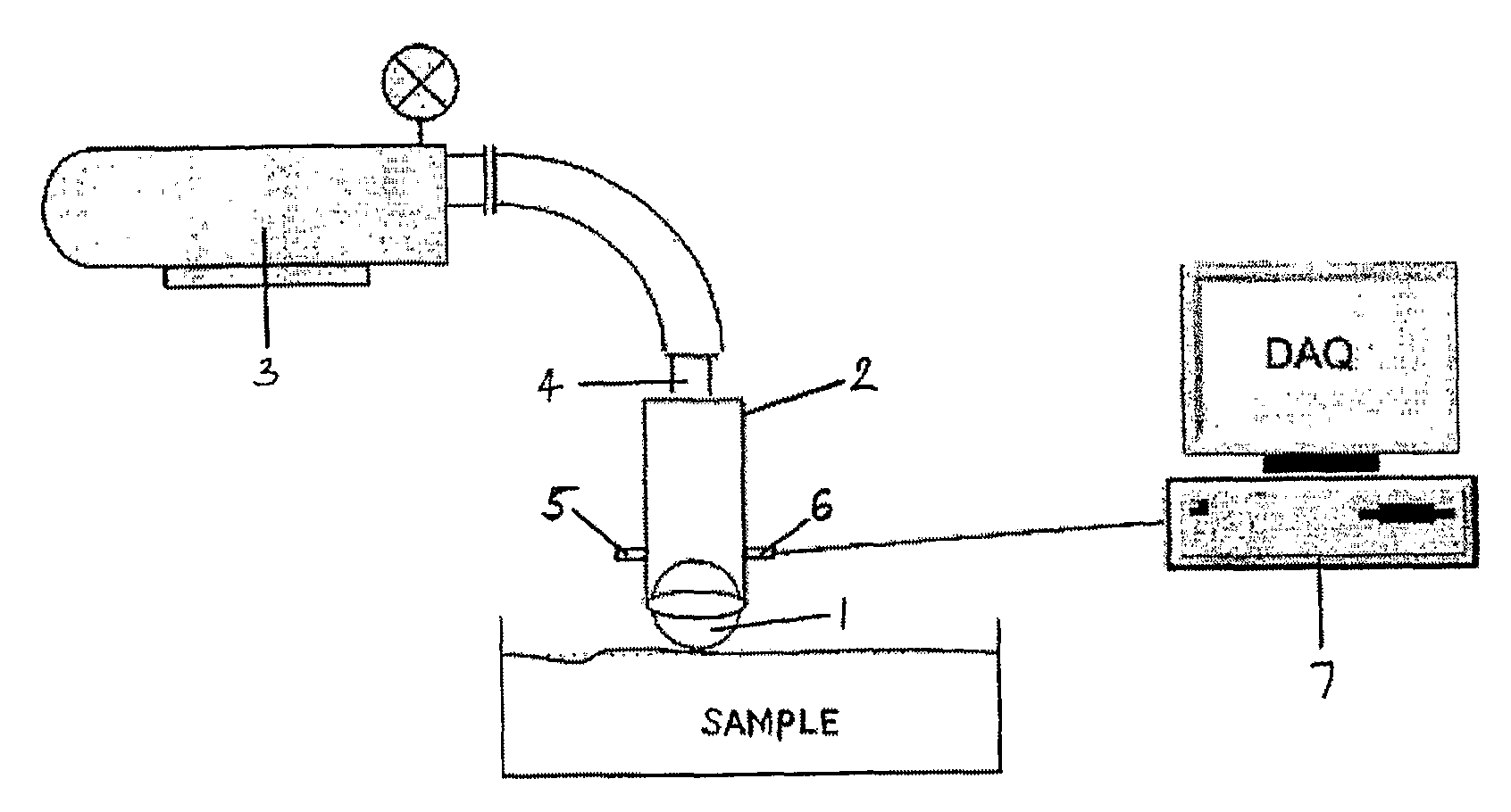
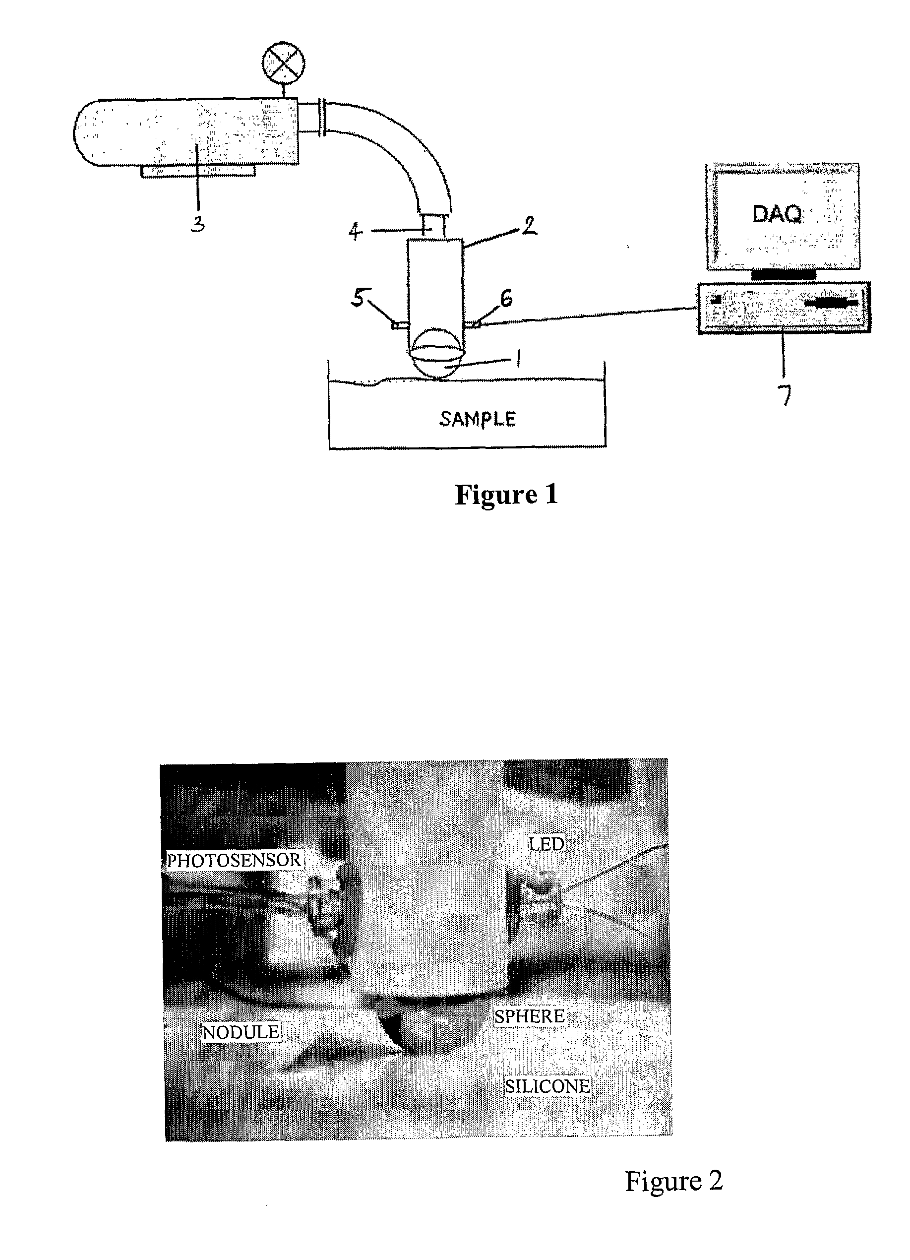
[0099]The sensor is a “sphere on air cushion” sensor which can be used as a stiffness and force sensor in MIS and can be used to measure the spatial stiffness / force distribution of soft tissue and identify tissue abnormalities during MIS. The sensor uses a freely moving sphere that can rotate on the spot and can be moved in any direction along a sample surface. More specifically, the sensor uses a sphere floating on an air-cushion to reduce friction and applies pressurized air onto the sphere to deform the tissue while the sensor is rolled over the surface.

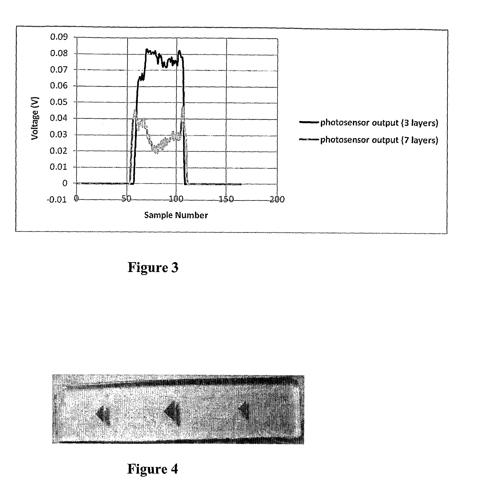
[0100]FIG. 1 shows a sensor comprising a 9 mm sphere 1 that is rolled over soft tissue to detect any abnormalities such as lumps. The sphere 1 is situated at the end of a hollow cylindrical shaft 2 with an inner diameter of 11.5 mm and “floats” on a cushion of air generated by an influx of air from a compressor 3 through an inlet 4 at the distal end of the shaft 2. An LED 5 and a photosensitive detector 6 are positioned in the sha...

example 2

[0118]Alternative Sensor

[0119]FIG. 9 shows an alternative sensor. The sensor comprises a 9 mm sphere 11 that is rolled over soft tissue to detect any abnormalities such as lumps. The sphere 11 is situated at the end of a hollow cylindrical shaft 12 with an inner diameter of 11.5 mm and “floats” on a cushion of air generated by an influx of air 13 from the distal end of the shaft 12. A light emitting fibre 14 and a light collecting fibre 15 are positioned on the shaft walls opposite each other just above the top of the sphere 11. Light is emitted from the light emitting fibre 14, is reflected off the sphere 11 and is collected by the light collecting fibre 15. The light emitting fibre 14 is connected to a light source, such as an LED or Laser. Light from the light source is transmitted through the light emitting fibre 14 onto the sphere 11. The light collecting fibre 15 is connected to a light sensitive sensor, such as a photo detector, light sensitive transistor or a light sensitive...

example 3

[0120]FIG. 11 shows another alternative sensor which is a variation of the sensor of Example 2. The sensor comprises a 9 mm sphere 11 that is rolled over soft tissue to detect any abnormalities such as lumps. The sphere 11 is situated at the end of a hollow cylindrical shaft 12 with a diameter of 11.5 mm and “floats” on a cushion of air generated by an influx of air 13 from the distal end of the shaft 12. A light emitting fibre 14 and a light collecting fibre 15 are positioned on the shaft walls opposite each other both just above a prism 16 and 17 respectively. Light that is shone from the light emitting fibre 14 is reflected off the prism 16 and has a trajectory which is perpendicular to the shaft walls. When the light beam reaches the prism 17 it is reflected straight onto the light collecting fibre thus generating an uninterrupted beam across the cylinder. As the sphere moves along the shaft walls, this beam is partially or fully interrupted which allows the light collecting fib...


PUM


Abstract

A sensor is described for detecting the force applied to or by soft material, and that is thus able to measure the stiffness of a soft material. The sensor comprises a sensor body into which is supplied a fluid under pressure. At least one sensor members are provided that are arranged to project from the sensor body under the pressure exerted thereon by the fluid. A sensor member displacement detection system is also provided, that is preferably optically based using optical fibres to illuminate the sensor member and that measures the modulation of the light reflected from the sensor member as the member is displaced against the pressure of the fluid to detect and measure the displacement. From the measured displacement an estimate of the force being applied to the sensor member can be obtained. The sensor is of a small size suitable for use during MIS or catheterisation procedures. Preferably the sensor is constructed of non-metallic material such that it is MRI compatible.

Description

TECHNICAL FIELD[0001]The invention relates to a sensor for providing force feedback, and in particular although not exclusively during surgical procedures. More specifically, one embodiment of the invention relates to a sensor for measuring variations in the stiffness of soft tissue for use in, for example, minimally invasive surgery or catheterisation. Another embodiment relates to a sensor for sensing the force on vasculature or other body channel walls during catheterisation procedures.BACKGROUND TO THE INVENTION AND PRIOR ART[0002]Minimally Invasive Surgery[0003]Minimally invasive surgery (MIS) can be described as a form of surgery that is performed through a number of small incisions. The incisions vary in sizes ranging from 3-12 mm in diameter [3]. The incisions are strategically located so as to offer access to the surgical site. A camera is initially inserted through one of the incisions to obtain a field of view of the surgical site. Laparoscopic tools are then inserted thr...

Claims


Application Information

Patent Timeline
IPC IPC(8): A61B5/103G01N3/42
CPCA61B5/103A61B5/6885A61B2562/168G01N2203/0089A61M2205/3344G01N3/42G01N33/4833A61M2025/0002
Inventor ALTHOEFER, KASPARZBYSZEWSKI, DINUSHAPUANGMALI, PINYOPOLYGERINOS, PANAGIOTISSENEVIRATNE, LAKMAL
Owner KING'S COLLEGE LONDON
Why Eureka
Try Eureka