
Waste heat recovery system

a heat recovery system and waste heat technology, applied in steam engine plants, machines/engines, mechanical equipment, etc., can solve the problems of increased retail price, increased cost increased costs of power generating systems, and increased costs of vehicles

Active Publication Date: 2011-03-31
SANCHEZ SANDRA I
View PDF42 Cites 29 Cited by
  • Summary
  • Abstract
  • Description
  • Claims
  • Application Information

AI Technical Summary

Benefits of technology

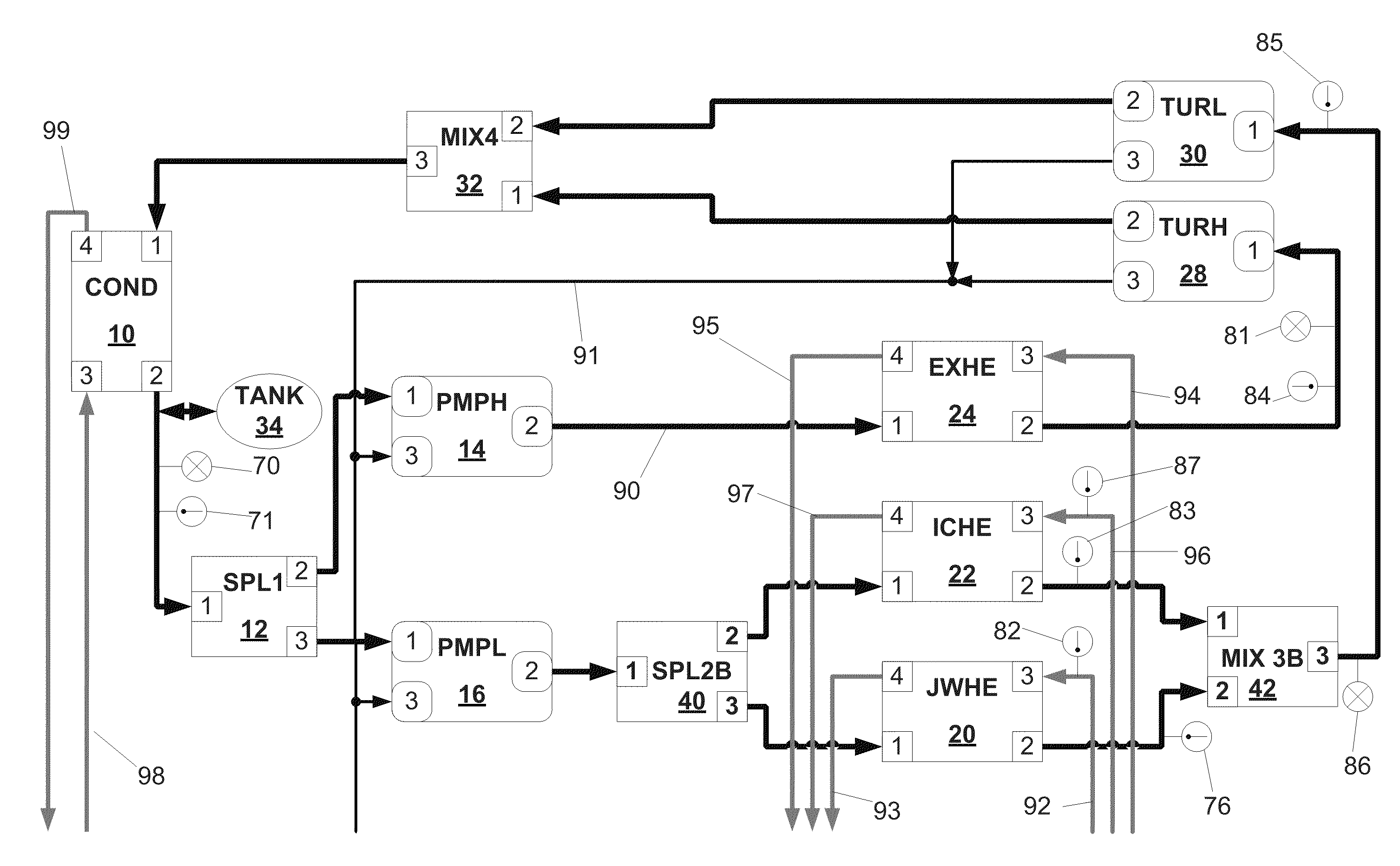
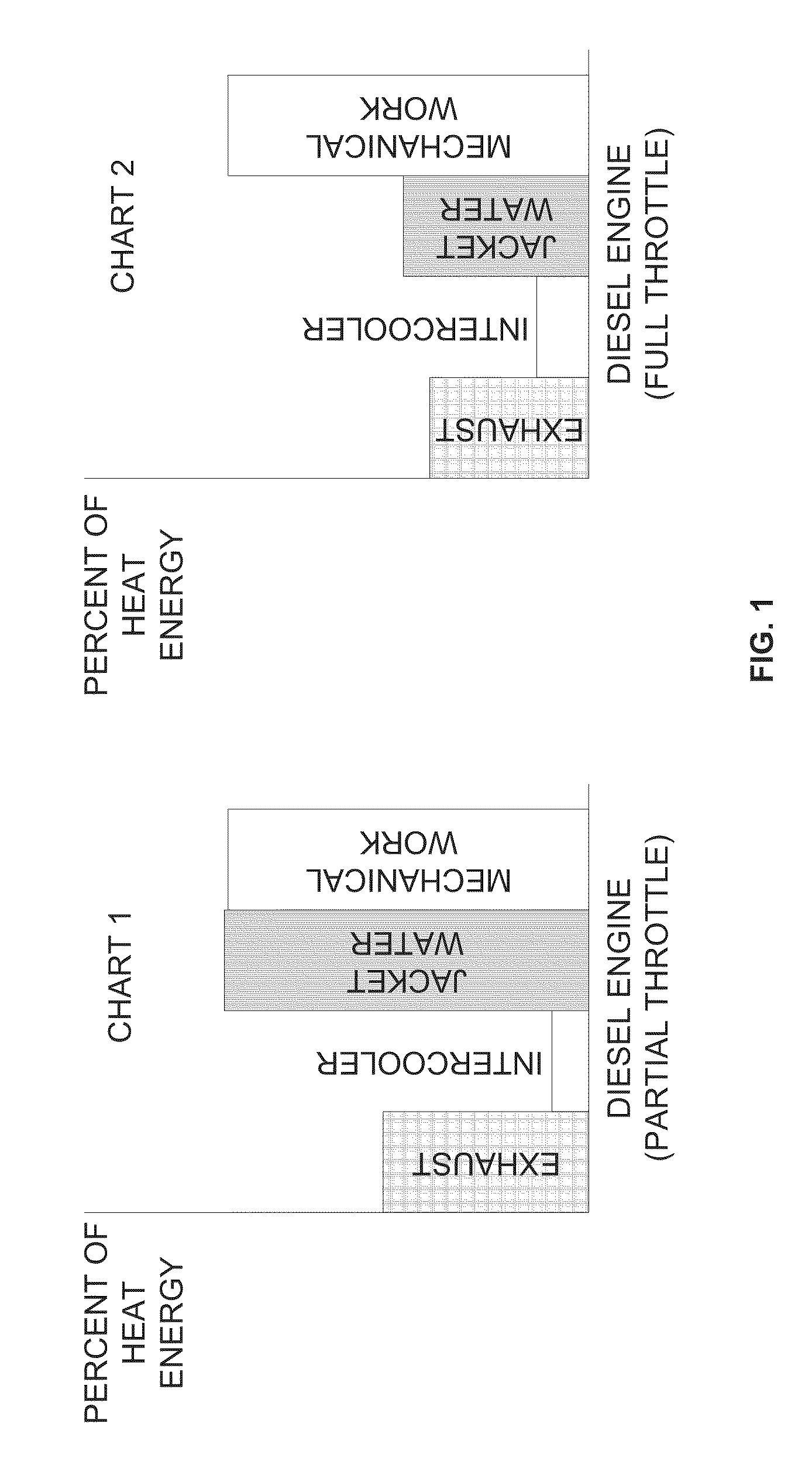
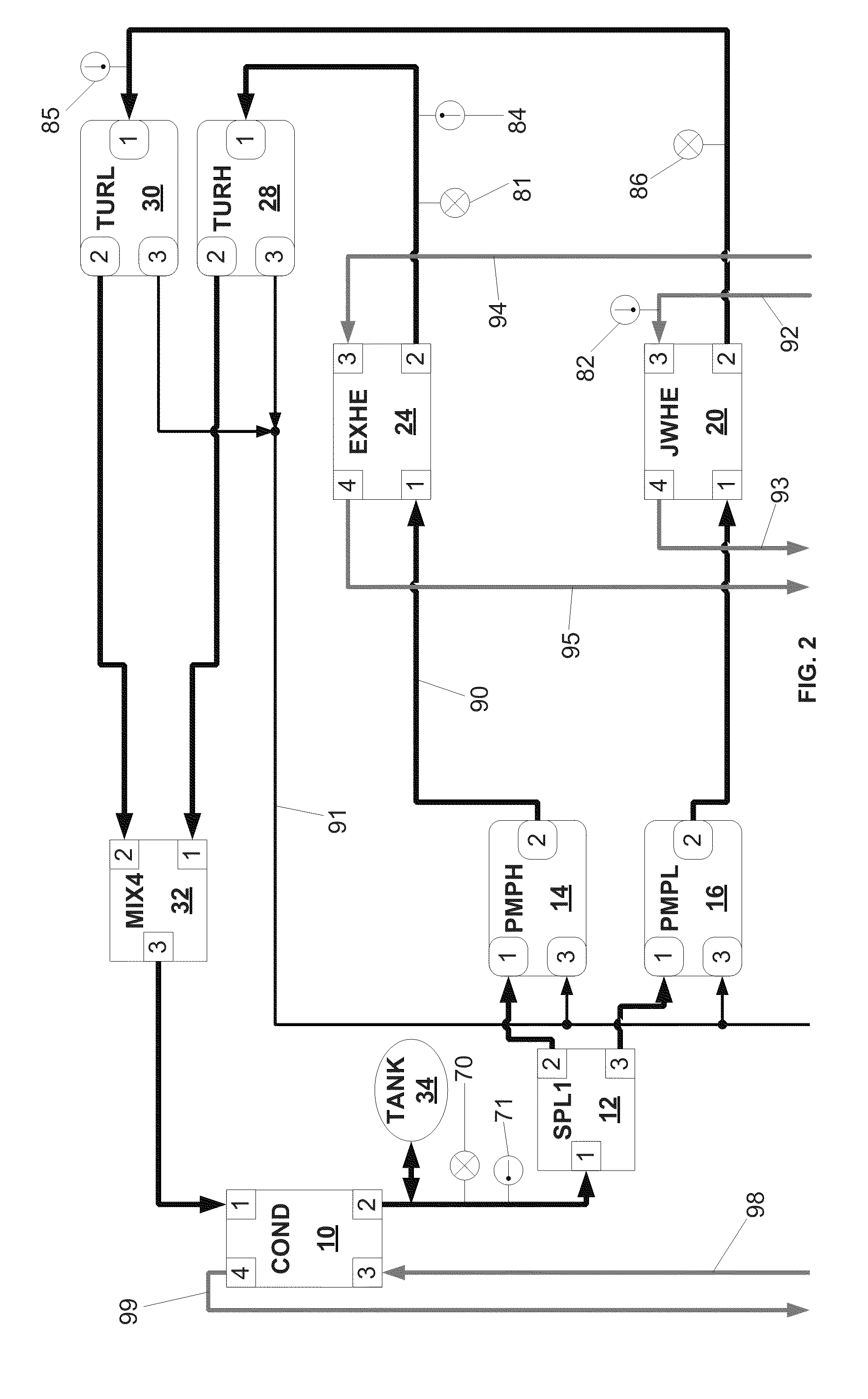
[0011]As compared to previously disclosed waste heat recovery systems, an advantage of the present invention is the elimination of additional heat exchangers required by said previously disclosed systems when the cycle could not absorb all of the jacket water heat energy or the charge air heat energy. The present invention employs a single working fluid with dual pressure circuits. This lowers the complexity, cost and weight by using a single condenser, condenser cooling circuit, working fluid reservoir, and low pressure control system. In one embodiments, the dual high pressure circuits allow for a low temperature and pressure boiling circuit to absorb all of the waste heat from the jacket water cooling media which has a peak temperature of approximately 95C, and a second higher temperature and pressure boiling circuit to absorb the heat from the charge air and exhaust gas flows which reach temperatures up to 250 C and 600 C respectively. The higher temperature and pressure of the second circuit allows it to run at a thermal efficiency almost twice as high as the lower temperature system.
is the elimination of additional heat exchangers required by said previously disclosed systems when the cycle could not absorb all of the jacket water heat energy or the charge air heat energy. The present invention employs a single working fluid with dual pressure circuits. This lowers the complexity, cost and weight by using a single condenser, condenser cooling circuit, working fluid reservoir, and low pressure control system. In one embodiments, the dual high pressure circuits allow for a low temperature and pressure boiling circuit to absorb all of the waste heat from the jacket water cooling media which has a peak temperature of approximately 95C, and a second higher temperature and pressure boiling circuit to absorb the heat from the charge air and exhaust gas flows which reach temperatures up to 250 C and 600 C respectively. The higher temperature and pressure of the second circuit allows it to run at a thermal efficiency almost twice as high as the lower temperature system.

Problems solved by technology

These impacts include an increase in the cost of transporting goods (which, in turn, leads to increases in retail prices, i.e., inflation), increased global tensions (as a large fraction of known oil reserves are located in tumultuous regions of the globe), and increased cost of power generating systems, including vehicles, (due to the need to add ever more complex, and costly, exhaust treatment systems).

Method used


Image

  • Waste heat recovery system
  • Waste heat recovery system
  • Waste heat recovery system

Examples


Embodiment Construction

[0034]To facilitate an understanding of the present disclosure, a number of terms and phrases are defined below:

[0035]Heat engine: A combination of components used to extract useful energy from one or more heat sources.

[0036]Internal combustion engine (ICE): A device that produces mechanical power by internally combusting a mixture of atmospheric air and fuel. Among others, types of ICEs include piston operated engines and turbines. Piston operated engines may be spark or compression ignited. Fuels used by ICEs include gasoline, Diesel, alcohol, dimethyl ether, JP8, biodiesel, various blends, and the like.

[0037]Rankine cycle: A thermodynamic cycle used to create work from heat. It is accomplished by pressurizing a working fluid, heating it so that it at least partially vaporizes, and then expanding it through an expander to extract heat energy. After expansion, the working fluid is condensed again to run through the cycle. The Rankine cycle described in this application is a closed ...


PUM


Abstract

To mitigate the potential significant impact on our society due to the continued reliance on high-cost diesel hydrocarbon fuel and the implementation of increasingly strict emission controls, an apparatus is disclosed which provides the means for extracting additional heat from an internal combustion engine while providing the cooling needed to meet stricter emissions standards. The present disclosure describes an apparatus operating on a Rankine cycle for recovering waste heat energy from an internal combustion engine, the apparatus including a closed loop for a working fluid with a single shared low pressure condenser serving a pair of independent high pressure circuits each containing zero or more controlled or passive fluid splitters and mixers, one or more pressure pumps, one or more heat exchangers, and one or more expanders, and the means for controlling said apparatus.

Description

CROSS-REFERENCE TO RELATED APPLICATIONS[0001]This application claims the benefit of U.S. Provisional Application No. 61 / 244,106, filed on Sep. 21, 2009, the entirety of which is incorporated herein by reference.BACKGROUND OF THE INVENTION[0002]The present invention relates to a waste heat recovery system for combustion engines and a method of controlling said waste heat recovery system.[0003]The continued reliance on high-cost diesel hydrocarbon fuel and the implementation of increasingly strict emission controls have had, and will continue to have, a significant impact on our society. These impacts include an increase in the cost of transporting goods (which, in turn, leads to increases in retail prices, i.e., inflation), increased global tensions (as a large fraction of known oil reserves are located in tumultuous regions of the globe), and increased cost of power generating systems, including vehicles, (due to the need to add ever more complex, and costly, exhaust treatment syste...

Claims


Application Information

Patent Timeline
IPC IPC(8): F01K13/00F01K23/06
CPCF01K13/02F01K25/10F01K23/065
Inventor COOK, DAVID
Owner SANCHEZ SANDRA I
Learn More