Oxyfuel Combustion Boiler Plant

a boiler plant and oxyfuel technology, applied in the direction of combustion types, emission prevention, lighting and heating apparatus, etc., can solve the problems of abnormal combustion, backfire, pulverized coal entering, etc., and achieve the effect of improving the ignition property of the burner

Active Publication Date: 2011-03-31
MITSUBISHI POWER LTD
View PDF3 Cites 19 Cited by
  • Summary
  • Abstract
  • Description
  • Claims
  • Application Information

AI Technical Summary

Benefits of technology

According to the present invention, an oxyfuel combustion boiler plant for improving the ignit...

Problems solved by technology

However, when injecting oxygen toward the mixture flow of pulverized coal and combustion exhaust gas, there are possibilities that pulverized coal may enter a mass of gas having a high oxygen ...

Method used


Image

  • Oxyfuel Combustion Boiler Plant
  • Oxyfuel Combustion Boiler Plant
  • Oxyfuel Combustion Boiler Plant

Examples


embodiment 1

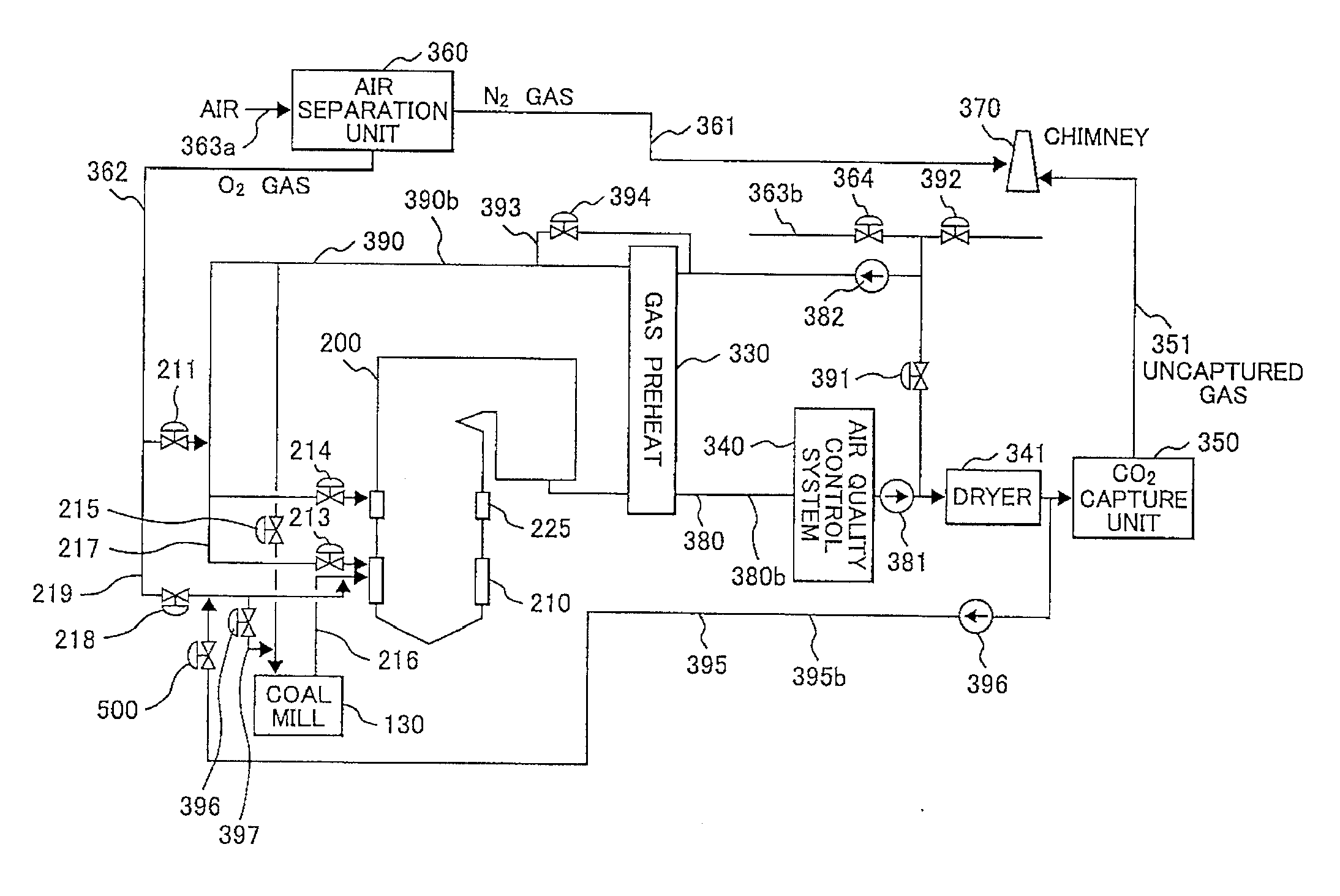
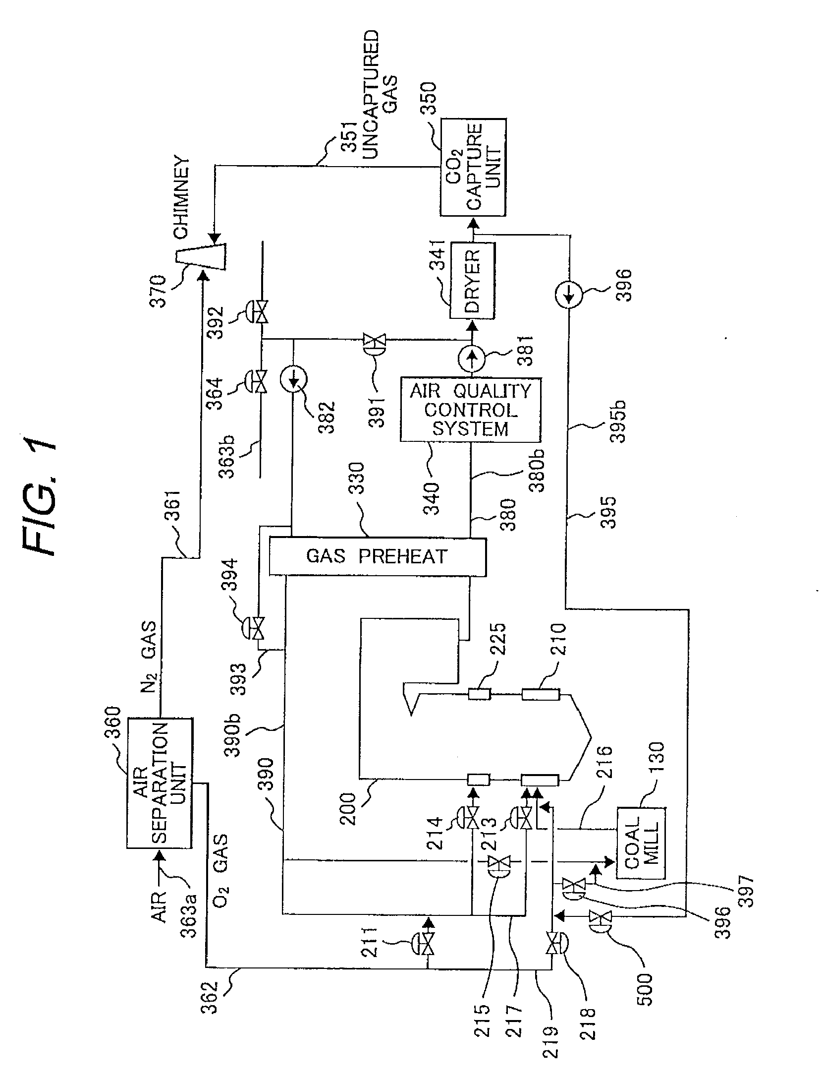
FIG. 1 shows the oxyfuel combustion boiler plant using coal as fuel. This embodiment is a thermal power plant for generating steam using a boiler 200.

The boiler 200 includes a burner 210 and a gas port 225. The burner 210 supplies and burns pulverized coal to the furnace in the boiler. The gas port 225 is disposed on the downstream side of the burner 210 and supplies second stage combustion gas to the furnace.

The system through which combustion exhaust gas discharged from the boiler 200 flows will be explained below. A combustion exhaust gas pipe 380b indicates the pipe through which the exhaust gas 380 discharged from the boiler 200 flows. An air quality control unit 340 is an apparatus for purifying exhaust gas 380. A fan 381 is a unit for letting exhaust gas flow. A dryer 341 cools exhaust gas 380 and simultaneously removes hygroscopic moisture. A CO2 capture unit 350 compresses exhaust gas 380 after drying and captures carbon dioxide from the exhaust gas 380. Uncaptured gas 351 ...

embodiment 2

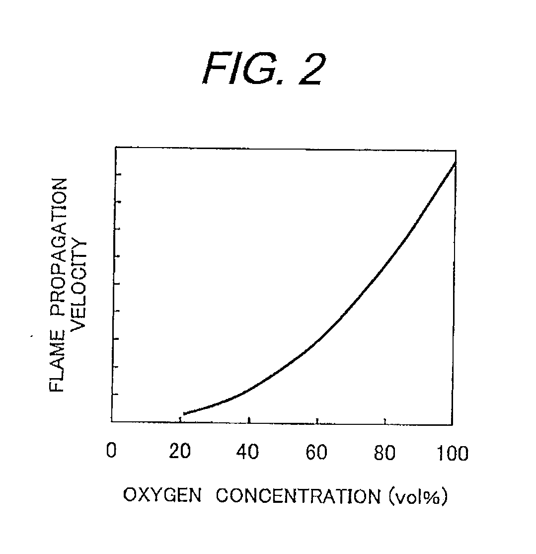
FIGS. 3 and 4 show a modification of the method for supplying a small quantity of the combustion exhaust gas 395. In FIG. 3, among the circulation exhaust gas 390, a part of the low-temperature circulation exhaust gas 393 not passing through the gas preheater 330 is branched and is supplied to the first oxygen supply pipe 219 through the pipe 395c. By use of the low-temperature exhaust gas, the effect of decreasing the flame propagation velocity is increased.

FIG. 4 shows a method for branching a part of the circulation exhaust gas 390 supplied to the first oxygen supply pipe 219 through the pipe 395d which is branched from the pipe 390b which supplies the circulation exhaust gas 390 to the coal mill 130. The temperature of the exhaust gas is raised, so that the effect of decreasing the flame propagation velocity is slightly inferior, though the pipe length can be shortened. Further, the method is suitable for a system using coal of an inferior ignition property.

embodiment 3

FIG. 5 shows a burner configuration example when the system shown in FIGS. 1 to 4 is applied.

A starting oil burner 22 is installed at the central part of the burner. Further, an oxygen-enriched gas injection nozzle 23 is installed around the oil burner 22. Further, the oxygen-enriched gas injection nozzle 23 is installed at the leading edge of the first oxygen supply pipe 219. Around the oxygen-enriched gas injection nozzle 23, a primary nozzle 25 is installed and the primary nozzle 25 injects primary gas 10 that is a mixture of pulverized coal 9 and combustion exhaust gas 11 into a boiler furnace 1. Oxygen-enriched gas 24 is supplied from the inside of the primary gas 10 injected circularly. Secondary gas 217a is supplied from the circumference of the primary nozzle 25 into the boiler furnace 1. The secondary gas 217a is branched to two flow paths via a wind box 2, then is given the swirl component of the flow by a swirl vane 17, and is supplied into the boiler furnace 1. The prima...


PUM


Abstract

An oxyfuel combustion boiler plant comprising: an air separation unit for manufacturing oxygen by separating nitrogen from air, a boiler having a burner for burning the oxygen supplied from the air separation unit and pulverized coal, and a primary system pipe for supplying the pulverized coal to the burner, an exhaust gas recirculation system pipe for supplying combustion exhaust gas discharged from the boiler to the primary system pipe, and a carbon dioxide capture unit for capturing carbon dioxide in the exhaust gas discharged from the boiler, the oxyfuel combustion boiler plant is further comprising: an oxygen supply pipe for supplying the oxygen manufactured by the air separation unit to the primary system pipe in the burner, and a pipe for supplying the combustion exhaust gas discharged from the boiler to the oxygen supply pipe, wherein an injection port of the oxygen supply pipe is disposed on an upstream side of an injection portion of the burner.

Description

CLAIM OF PRIORITYThe present application claims priority from Japanese patent application serial No. 2009-225902, filed on Sep. 30, 2009, the content of which is hereby incorporated by reference into this application.BACKGROUND OF THE INVENTION1. Field of the InventionThe present invention relates to an oxyfuel combustion boiler plant.2. Description of Related ArtA boiler for burning pulverized coal can be divided into two kinds of combustion systems depending on the gas to be supplied to a burner. Air-fuel combustion is of a system for burning fuel by supplying air to the burner. Further, oxyfuel combustion is of a system far burning fuel by a mixture of high purity oxygen and combustion exhaust gas instead of air.In the oxyfuel combustion, the exhaust gas components are mostly carbon dioxide, so that when capturing carbon dioxide from exhaust gas, there is no need to concentrate the carbon dioxide. Therefore, the oxyfuel combustion can pressurize and cool the exhaust gas as it is ...

Claims


Application Information

Patent Timeline
IPC IPC(8): F23C9/00F23J15/00F23L7/00F23L15/00F23K3/02
CPCF23C9/003F23C2202/10F23C2900/06041F23J2215/50F23D1/00F23L2900/07001F23L2900/07005Y02E20/322Y02E20/344F23L7/007Y02E20/32Y02E20/34
Inventor TANIGUCHI, MASAYUKISHIBATA, TSUYOSHIHAYASHI, YOSHIHARU
Owner MITSUBISHI POWER LTD
Why Eureka
Try Eureka